
Aerospace manufacturing is increasingly focused on structural weight reduction, material efficiency, integrated component design and advanced manufacturing processes. Composite materials are central to this transition, creating new requirements for tooling accuracy, thermal stability and process control.
For composite mold manufacturers, the challenge is no longer limited to producing a mold with the correct geometry. Aerospace-related tooling projects may require coordinated engineering across material behavior, thermal expansion, mold stiffness, resin flow, pressure distribution and dimensional verification.
This article examines the major aerospace composite tooling trends in 2026 and explains the engineering considerations behind molds for carbon fiber composites, electric vertical take-off and landing (eVTOL) platforms, thermoplastic composites and other advanced applications.
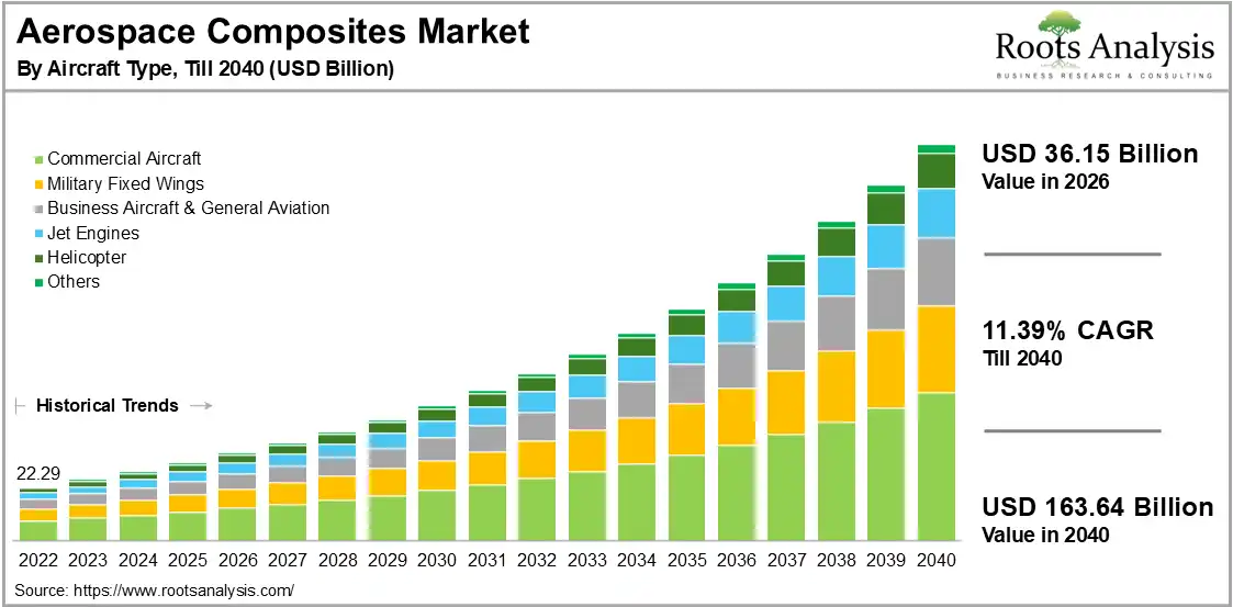
1. Why Aerospace Composite Tooling Is Becoming More Important
Aircraft manufacturers are under continuous pressure to improve structural efficiency, reduce component weight and optimize production costs. Composite materials offer a combination of low density, high specific strength, corrosion resistance and design flexibility that makes them suitable for many aerospace applications.
However, composite material performance depends not only on the material itself. The molding process, tooling geometry, temperature history, pressure distribution and curing or consolidation conditions also influence the final component.
This makes aerospace composite molds an important part of the manufacturing system. A poorly designed tool can introduce dimensional variation, surface defects, inconsistent consolidation or difficulties during demolding.
Key manufacturing drivers
- Weight reduction: Lightweight composite structures help improve aircraft efficiency and payload performance.
- Structural integration: More complex geometries and integrated components require carefully engineered tooling.
- Dimensional consistency: Aerospace components often require controlled geometry and repeatable manufacturing conditions.
- Production efficiency: Manufacturers seek stable processes, shorter cycle times and reduced material waste.
- Advanced materials: New thermoplastic and high-performance composite systems create additional tooling challenges.
These trends are increasing demand for composite tooling that is designed around the actual material system and production process rather than geometry alone.
2. Aerospace Applications Driving Composite Mold Development
2.1 Commercial Aircraft Structures
Commercial aircraft use composite materials in a range of structural and non-structural components. Applications may include fuselage sections, wing structures, control surfaces, fairings, access panels and interior components.
Large composite structures present particular tooling challenges. Mold deflection, thermal gradients, part shrinkage and dimensional changes during cooling must be considered during tool design.
For large-format tooling, engineering evaluation should include structural stiffness, support configuration, heating strategy, measurement access and the expected manufacturing environment.
2.2 Electric Vertical Take-Off and Landing Aircraft (eVTOL)
The development of electric vertical take-off and landing aircraft is expanding the use of lightweight structures and complex composite geometries. Depending on the aircraft architecture, composite materials may be considered for fuselage panels, aerodynamic surfaces, structural covers, propulsion-related housings and other components.
Compared with conventional aircraft programs, some eVTOL projects place additional emphasis on rapid development, design iteration and scalable production. This creates demand for tooling strategies that balance prototype flexibility with production repeatability.
For eVTOL composite tooling, important considerations include:
- Complex component geometry and integrated features.
- Repeatable dimensional positioning and part alignment.
- Tool stiffness under the intended molding conditions.
- Thermal stability during heating and cooling.
- Practical demolding and handling arrangements.
- Potential transition from prototype tooling to production tooling.
2.3 Military and Specialized Aerospace Applications
Military and specialized aerospace platforms may use composite materials in structural panels, aerodynamic surfaces, protective housings and other application-specific components.
Tooling requirements vary significantly according to the component function, material specification and manufacturing route. Surface quality, dimensional stability, repeatability and process traceability may all be important.
The applicable technical requirements should be defined by the customer and the relevant program documentation. A tooling supplier should not assume aerospace qualification or product certification solely from its ability to manufacture composite molds.
2.4 Hydrogen and Electrified Aircraft Development
Electrified propulsion and hydrogen-related aircraft development may introduce new component architectures and material requirements. Composite materials can be considered for lightweight structures, enclosures, ducts and other engineered parts, depending on the design and operating environment.
These applications may require close attention to material compatibility, operating temperature, environmental exposure, structural requirements and manufacturing repeatability.
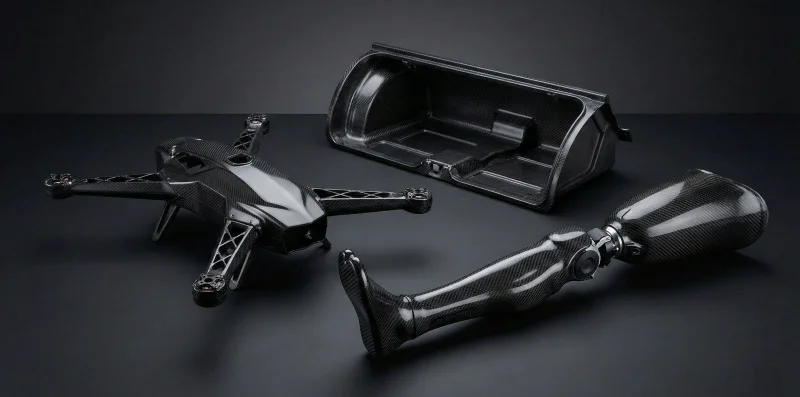
3. Aerospace Composite Materials and Their Tooling Requirements
Different composite materials behave differently during molding. Resin chemistry, reinforcement architecture, processing temperature, pressure and cooling behavior all influence tooling design.
3.1 Carbon Fiber Reinforced Polymer (CFRP)
Carbon fiber reinforced polymer is widely associated with high-performance aerospace structures because of its high specific strength and stiffness. CFRP components may be manufactured through processes such as prepreg layup and autoclave curing, out-of-autoclave processing, resin transfer molding and compression molding.
Carbon fiber tooling requirements depend on the selected manufacturing route. Important factors include:
- Thermal expansion compatibility between the mold and composite material.
- Tool stiffness under vacuum, pressure or other process loads.
- Surface quality and release-system compatibility.
- Temperature distribution across the working surface.
- Dimensional compensation for thermal changes and material shrinkage.
A mold designed for one CFRP process should not automatically be assumed suitable for another. Prepreg curing, RTM and compression molding can impose different requirements on tooling construction and process control.
3.2 Thermoplastic Composites: PEEK, PEKK and PPS
High-performance thermoplastic composites are attracting attention in aerospace and advanced mobility applications. Materials such as PEEK, PEKK and PPS offer application-dependent combinations of mechanical performance, chemical resistance and processing characteristics.
Compared with many thermoset systems, thermoplastic composite forming can involve different heating, consolidation and cooling cycles. Tooling must therefore be designed around the actual resin grade, reinforcement architecture and process window.
Key tooling considerations include:
- Thermal stability at the specified processing temperature.
- Tool material selection and thermal expansion behavior.
- Heating and cooling system design.
- Temperature uniformity across the forming surface.
- Pressure transmission and consolidation behavior.
- Dimensional stability after repeated thermal cycles.
A tooling specification should identify the exact thermoplastic material and processing conditions. The names PEEK, PEKK and PPS alone are not sufficient to define a mold's operating requirements.
3.3 SMC and BMC Composite Materials
Sheet Molding Compound (SMC) and Bulk Molding Compound (BMC) are fiber-reinforced thermoset materials used in compression molding. Their processing characteristics make them suitable for selected complex molded components and applications requiring integrated features.
SMC and BMC tooling typically requires attention to material placement, flow behavior, venting, flash control, mold temperature and curing consistency.
Depending on the component design, the mold may need to accommodate:
- Controlled material charge placement.
- Flow paths around ribs, bosses and other geometric features.
- Air evacuation and venting.
- Parting-line design and flash management.
- Demolding features and ejector arrangements.
- Repeatable mold temperature and closing conditions.
For background on compression mold engineering, see the compression mold guide and SUASE's overview of SMC mold manufacturing.
3.4 Resin Transfer Molding (RTM) and Related Processes
Resin Transfer Molding (RTM) uses a closed mold to introduce resin into a dry fiber preform. The mold must support the required cavity geometry, resin distribution, sealing and venting conditions.
RTM tooling design may involve:
- Resin inlet and distribution arrangements.
- Venting and air evacuation locations.
- Sealing interfaces and mold closure.
- Parting-line accuracy and cavity alignment.
- Tool stiffness under the specified injection and clamping loads.
- Temperature management where heated tooling is required.
Injection pressure and process temperature should be established from the resin system, preform permeability, component geometry and process validation. A universal pressure range should not be used as a substitute for project-specific engineering.
4. Aerospace Composite Mold Engineering: Key Design Requirements
4.1 Thermal Expansion and CTE Matching
The coefficient of thermal expansion (CTE) describes how a material changes dimension as its temperature changes. In composite mold design, the thermal expansion behavior of the tool must be evaluated against the composite material and the intended manufacturing cycle.
A mismatch in thermal expansion can contribute to dimensional deviation, residual stress and warpage during heating and cooling.
CTE evaluation should consider:
- Tool material and its temperature-dependent expansion behavior.
- Composite reinforcement direction and laminate architecture.
- Resin system and curing or consolidation behavior.
- Processing temperature and cooling profile.
- Part geometry and dimensional measurement conditions.
- Required final dimensions at the specified reference temperature.
For anisotropic composite laminates, expansion may differ along different material directions. Consequently, CTE matching should be assessed as part of the complete tooling and material system, rather than through a single material coefficient.
4.2 Mold Stiffness and Structural Stability
Tool deformation under operating loads can directly affect the geometry of the molded component. This is particularly important for large molds, thin-wall components and processes involving vacuum, injection pressure or substantial clamping forces.
Structural design should consider:
- Tool base and cavity support structure.
- Load distribution across the mold surface.
- Local deformation around deep cavities and large openings.
- Clamping and alignment arrangements.
- Support points and handling loads.
- Thermal deformation during the complete process cycle.
Structural analysis can help identify areas of potential deformation before machining and trial production. The analysis assumptions should reflect the actual boundary conditions, operating loads and temperature conditions.
4.3 Heating and Cooling System Design
Temperature control affects resin flow, curing, consolidation and dimensional stability. Uneven temperature distribution may lead to inconsistent material behavior across the component.
Depending on the process, tooling may use electrical heating, thermal oil circulation or other engineered heating arrangements. The appropriate solution depends on the required temperature range, mold structure, process cycle and production environment.
Heating and cooling design should evaluate:
- Heating-zone layout and temperature distribution.
- Sensor locations and temperature feedback.
- Thermal expansion of the mold structure.
- Heating and cooling cycle requirements.
- Accessibility for maintenance and inspection.
- Temperature variation between different cavity regions.
The required temperature uniformity should be specified and verified using an agreed measurement method. A temperature controller setting alone does not demonstrate uniform mold-surface temperature.
4.4 Vacuum, Sealing and Venting
Vacuum and sealing requirements depend on the manufacturing process. Prepreg processing, vacuum-assisted manufacturing and RTM may require different sealing arrangements and air evacuation strategies.
For closed-mold processes, sealing surfaces and parting-line geometry should be designed to maintain the specified process conditions. Venting locations should be considered alongside resin flow and potential air-trapping areas.
Poorly positioned vents may contribute to air entrapment, incomplete filling or surface defects. In compression molding, insufficient venting can also affect material flow and local consolidation.
4.5 Surface Finish and Demolding
Mold surface quality influences the appearance and surface characteristics of the final composite component. The required finish depends on the component function, downstream coating or bonding operations and customer acceptance criteria.
Demolding design should also account for draft angles, undercuts, release systems, part geometry and the mechanical behavior of the composite during cooling.
For complex components, demolding arrangements should be reviewed during the design stage rather than added only after the first trial.
5. Aerospace Composite Tooling Selection Matrix
There is no single mold construction suitable for every aerospace composite application. The tooling approach should be selected according to material behavior, manufacturing process, component geometry and production objectives.
| Application or Process | Main Tooling Challenges | Engineering Considerations |
|---|---|---|
| eVTOL Composite Structures | Complex geometry, dimensional consistency and development speed. | Tool stiffness, thermal stability, positioning accuracy, surface quality and demolding access. |
| High-Performance Thermoplastics (PEEK / PEKK / PPS) | High processing temperatures, thermal cycling and consolidation. | Tool material selection, CTE evaluation, heating and cooling design, thermal stability and process-specific pressure requirements. |
| RTM Composite Components | Resin distribution, air evacuation and cavity sealing. | Injection layout, venting, sealing interfaces, mold closure and structural stiffness. |
| CFRP Thermoset Components | Curing shrinkage, thermal expansion and residual stress. | CTE compatibility, thermal compensation, surface finish and curing-cycle control. |
| Large Composite Panels | Tool deflection, temperature gradients and handling complexity. | Structural support, thermal-zone layout, deformation evaluation and measurement strategy. |
| SMC / BMC Compression Molded Parts | Material flow, trapped air, flash and curing consistency. | Charge placement, venting, parting-line design, mold temperature and demolding arrangements. |
This matrix provides a general engineering reference. Final tooling specifications must be established from the component drawings, material data, process parameters and customer requirements.
6. Prototype Development vs. Production Composite Tooling
Aerospace and advanced air mobility programs may require several development stages before reaching stable production. The tooling strategy should reflect the purpose of each stage.
6.1 Prototype Tooling
Prototype tooling is generally intended to support early-stage development, geometry verification, material evaluation and manufacturing-process trials.
Depending on the project, prototype tooling may prioritize design flexibility, shorter development lead times and convenient access for modifications.
6.2 Production Tooling
Production tooling is developed around repeatable manufacturing conditions and the expected production environment. More attention may be required for tool durability, maintenance access, thermal consistency, automation interfaces and process repeatability.
6.3 Why the Transition Should Be Planned Early
A prototype mold should not automatically be treated as a production mold. Differences in production volume, cycle time, automation, inspection requirements and maintenance strategy can lead to substantial changes in tooling design.
Early discussion of the intended production scale can help avoid unnecessary redesign when a component moves from development to manufacturing.
7. Common Aerospace Composite Molding Problems and Their Engineering Causes
Composite part defects can originate from material preparation, process parameters, mold design or the interaction between these factors. Tooling-related causes should be investigated systematically.
| Observed Problem | Possible Engineering Causes | Recommended Investigation |
|---|---|---|
| Part warpage after cooling | Thermal expansion mismatch, uneven cooling, residual stress or asymmetric laminate structure. | Review CTE assumptions, temperature history, cooling sequence and laminate orientation. |
| Dimensional deviation | Tool deformation, thermal compensation errors or inconsistent process conditions. | Check mold geometry, support stiffness, operating temperature and measurement reference conditions. |
| Surface defects | Tool surface damage, trapped air, contamination or unsuitable release conditions. | Inspect cavity finish, vent locations, cleaning procedures and release-system compatibility. |
| Incomplete resin filling | Insufficient resin distribution, unsuitable flow path or blocked venting. | Review injection and venting layout, preform permeability and process parameters. |
| Uneven curing or consolidation | Temperature gradients, inconsistent pressure transmission or process variation. | Evaluate temperature mapping, heating-zone design and pressure distribution. |
| Demolding difficulty | Insufficient draft, undercuts, unsuitable release conditions or part shrinkage. | Review mold geometry, release strategy and demolding sequence. |
Corrective action should be based on evidence from process records, dimensional inspection and mold evaluation. Changing mold geometry without identifying the underlying cause may introduce additional variation.
8. How to Evaluate an Aerospace Composite Mold Manufacturer
Selecting an aerospace composite tooling supplier requires more than comparing quotations. Buyers should evaluate whether the manufacturer can understand the material system, translate requirements into tooling specifications and support the intended manufacturing process.
8.1 Engineering and Design Capability
Evaluate the supplier's ability to review 2D drawings, 3D CAD data, material specifications and process requirements. A capable engineering team should be able to identify potential tooling challenges before manufacturing begins.
8.2 Machining and Manufacturing Capability
Tool manufacturing involves material preparation, machining, assembly, fitting and inspection. Buyers should confirm that the supplier's equipment, machining envelope and inspection resources are appropriate for the actual mold dimensions and tolerances.
8.3 Process Understanding
A mold designed for SMC compression molding may require different features from an RTM tool or a thermoplastic forming tool. Suppliers should demonstrate an understanding of the intended process rather than relying on a generic mold design approach.
8.4 Inspection and Quality Documentation
Buyers should define inspection requirements before production. Depending on the project, documentation may include dimensional inspection results, material records, machining inspection, assembly checks and trial-production observations.
8.5 Aerospace Qualification and Program Requirements
A composite tooling manufacturer and an aerospace-certified component manufacturer are not necessarily the same type of supplier. Tooling capability alone does not establish airworthiness approval, aerospace product certification or qualification for a specific aircraft program.
If a project requires specific quality-system approvals, traceability procedures, special-process controls or customer qualification, these should be confirmed independently and documented in the supplier evaluation process.
9. SUASE Mould: Composite Tooling Engineering and Manufacturing
SUASE Mould focuses on composite mold engineering and manufacturing, serving applications that require tooling for different reinforced composite materials and molding processes.
Its composite tooling scope includes mold solutions associated with SMC, BMC, GMT, LFT, PCM, Baypreg and other composite molding technologies, depending on project specifications.
For customers developing advanced composite components, tooling discussions should begin with the part geometry, material system, manufacturing process and production objectives.
Engineering considerations for custom tooling projects
- Part geometry review: Understand cavity geometry, ribs, bosses, undercuts and functional interfaces.
- Material and process evaluation: Identify the composite material, reinforcement architecture and molding route.
- Tool structure: Consider mold stiffness, support configuration and operating loads.
- Thermal design: Evaluate the heating and cooling requirements and thermal expansion behavior.
- Manufacturing planning: Review machining accessibility, assembly requirements and inspection points.
- Trial and verification: Define the inspection and process-validation criteria required by the customer.
SUASE's experience in composite mold manufacturing provides a foundation for discussing custom tooling requirements across different composite processes. The suitability of a particular solution must be evaluated against the specific application, material and customer specification.
Learn more about compression mold engineering and SMC mold manufacturing.
10. RFQ Checklist: Information Required for Aerospace Composite Mold Quotation
An accurate tooling quotation depends on complete technical input. When requesting a quotation for an aerospace-related composite mold, buyers should prepare the following information wherever available.
| RFQ Information | Details to Provide | Why It Matters |
|---|---|---|
| Part drawings | 2D engineering drawings and 3D CAD files. | Defines geometry, interfaces and dimensional requirements. |
| Composite material | Material grade, resin system, fiber type and reinforcement architecture. | Influences thermal behavior, flow, curing and consolidation. |
| Molding process | Prepreg curing, RTM, compression molding or thermoplastic forming. | Determines mold structure and process-related features. |
| Operating conditions | Required temperature, pressure, vacuum conditions and process cycle. | Defines the operating environment for the tool. |
| Dimensional requirements | Critical dimensions, tolerances and reference measurement temperature. | Supports tool compensation and inspection planning. |
| Surface requirements | Surface finish, appearance criteria and downstream coating or bonding requirements. | Influences cavity finishing and acceptance criteria. |
| Production volume | Prototype quantity, annual demand and expected tool life. | Helps determine tooling construction and durability requirements. |
| Equipment interface | Press dimensions, platen layout, clamping interface and available utilities. | Ensures compatibility with the intended production equipment. |
| Inspection requirements | Dimensional reports, material documentation and trial acceptance criteria. | Defines the required verification and documentation scope. |
| Project schedule | Design review, tooling delivery, trial and production milestones. | Supports realistic manufacturing planning. |
If some technical information is not yet available, buyers can provide preliminary drawings and project requirements for an initial engineering discussion. Critical process parameters should be confirmed before the final tooling specification and quotation are established.
11. Future Trends in Aerospace Composite Tooling
11.1 Greater Use of Thermoplastic Composite Processes
Thermoplastic composites are expected to remain an important area of aerospace materials development. Their potential advantages in selected manufacturing and joining applications are encouraging continued process development.
For tooling manufacturers, this means greater attention to high-temperature material behavior, thermal cycling, cooling control and repeatable consolidation.
11.2 More Integrated and Complex Component Geometry
Component integration can reduce the number of separate parts and assembly operations. However, more complex geometry may increase the difficulty of mold design, material placement, venting and demolding.
Tooling engineers will need to consider manufacturability earlier in the component development process.
11.3 Digital Engineering and Process Verification
CAD-based design, structural analysis, thermal simulation and dimensional inspection can support more systematic tooling development.
These methods are most useful when the simulation assumptions, material properties and boundary conditions are consistent with the real manufacturing process.
11.4 Greater Focus on Production Repeatability
As advanced air mobility and other aerospace-related programs develop, manufacturers may need to move from prototype production toward more repeatable manufacturing systems.
Tool durability, maintenance planning, process monitoring and inspection strategies will become increasingly important parts of the overall tooling discussion.
12. Frequently Asked Questions About Aerospace Composite Molds
Q1. What are aerospace composite molds used for?
Aerospace composite molds are used to manufacture composite components for aircraft and advanced air mobility applications. Depending on the material and process, they may support carbon fiber layup, resin transfer molding, compression molding and thermoplastic forming.
Q2. What materials are used to manufacture aerospace composite tooling?
Tooling materials may include aluminum alloys, steel, low-expansion alloys and other engineered materials. Selection depends on operating temperature, thermal expansion, stiffness, tooling size, production volume and the composite molding process.
Q3. Why is CTE matching important in aerospace composite mold design?
The coefficient of thermal expansion affects the dimensional relationship between the mold and composite part during heating and cooling. A mismatch can contribute to dimensional deviation, residual stress and warpage. CTE should therefore be evaluated against the material system, component geometry and process conditions.
Q4. Can the same mold be used for thermoset and thermoplastic composites?
Not necessarily. Thermoset and thermoplastic processes may involve different temperature profiles, pressure conditions, cooling requirements and material flow behavior. Tooling should be designed for the specific material and manufacturing process.
Q5. What information is needed to request an aerospace composite mold quotation?
A useful RFQ package includes 2D drawings or 3D CAD files, composite material specifications, molding process, target production volume, operating temperature, pressure requirements, dimensional tolerances, surface finish requirements and expected delivery schedule.
Q6. Does a composite mold supplier automatically qualify as an aerospace-certified manufacturer?
No. Manufacturing composite tooling does not automatically establish aerospace product certification, airworthiness approval or qualification for a particular aircraft program. These requirements must be evaluated separately for each project and supply chain.
Q7. What should buyers consider when selecting a mold for eVTOL composite parts?
Buyers should evaluate component geometry, material system, molding process, thermal stability, mold stiffness, dimensional requirements, demolding strategy and the expected transition from prototype to production.
Conclusion: Engineering the Next Generation of Aerospace Composite Tooling
The development of advanced aircraft and electric air mobility platforms is creating new opportunities for composite materials and specialized manufacturing processes.
However, successful composite production depends on more than material selection. Mold structure, thermal expansion, temperature distribution, resin flow, pressure transmission and dimensional verification all influence the final result.
For buyers evaluating aerospace composite molds, the most effective approach is to define the material system, manufacturing process and component requirements before selecting a tooling solution.
SUASE Mould focuses on composite tooling engineering and manufacturing for a range of reinforced composite molding applications. For custom tooling projects, early technical communication can help clarify mold construction, process requirements and manufacturing scope.
Discuss Your Composite Mold Project with SUASE
Are you developing a carbon fiber component, thermoplastic composite part, SMC/BMC molded component or another advanced composite application?
Share your 2D drawings, 3D CAD files, material specifications and expected production requirements with SUASE Mould. Our team can review the project information and discuss potential tooling design and manufacturing approaches based on your application.