In direct long-fibre thermoplastic (D-LFT) compression moulding, a ribbed component may leave the mould with a complete outline while its load-bearing performance remains unverified. Filling the cavity shows where the material arrived. The next question is how the finished component carries a load between its mounting points.
For a new D-LFT compression mould, review where the charge—the material placed in the mould—must flow and which regions of the part carry the important loads. A project review with SUASE, whose tooling range includes LFT moulds, can connect those requirements to the proposed cavity and rib layout.
Start with what the component has to carry
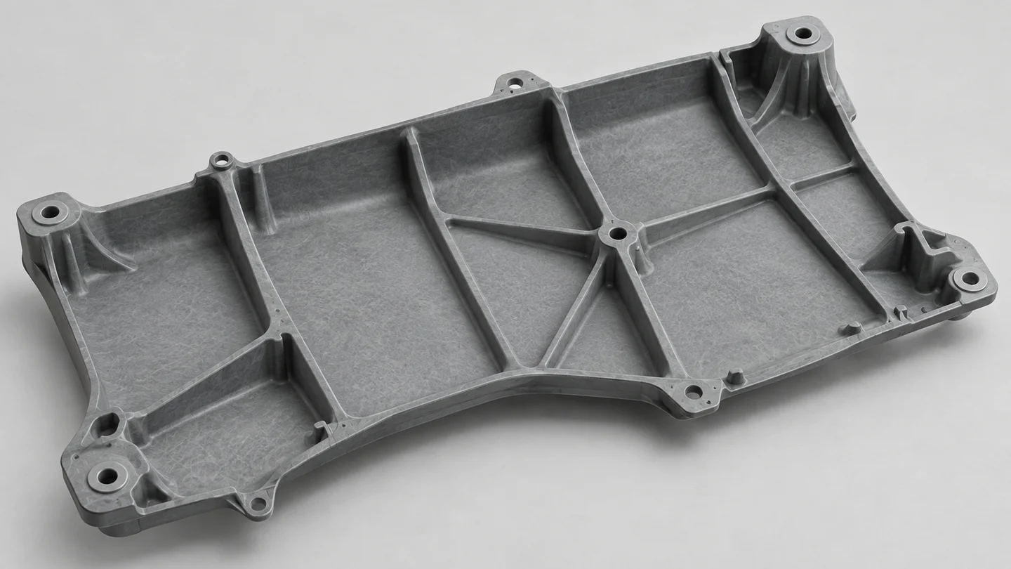
Before choosing a charge position, mark the supports and the important load directions on the part drawing. A load applied near a mounting boss presents a different question from bending across a broad panel. A rib that helps one loading condition may have little value for another.
Consider, for example, a proposed carrier with two supports and a central load. The engineering question is how force passes through the panel, ribs and connections to those supports. Reviewing that load path alongside the mould layout helps identify which regions deserve closer material and structural investigation before the tooling design is fixed.
That marked drawing gives a review with SUASE a specific focus: which loaded region needs attention, whether its geometry can change, and which material or assembly decisions also affect it.
A flow pattern is not a fibre map
Long-fibre thermoplastic properties depend on the material's internal fibre structure. Compression flow changes fibre orientation, so material properties should not simply be assumed identical in every direction. Research on LFT-D compression moulding has also found that the resulting orientation can deviate from the anticipated flow direction. Schelleis and colleagues, 2025.
For tooling development, this means that a filling pattern can help compare material routes, but local strength still requires suitable material data and structural assessment. A complete rib or smooth surface alone does not answer that question.
Where simulation is proposed, the project team should first confirm that the selected method and material inputs are suitable for the actual D-LFT process. The analysis scope, required data and responsibility for correlating predictions with samples should be agreed explicitly.
Compare charge options before committing to steel
Moving the charge can change the routes through which material reaches ribs, edges and mounting regions. A shorter route to one feature may create a less favourable route elsewhere. For that reason, a charge layout should be considered together with the functional geometry, rather than selected only to achieve a complete fill.
A focused review with SUASE can start from two candidate layouts and one clearly defined concern: for example, the region around a loaded support. The discussion can then identify which differences require forming analysis, a trial observation or a structural test. The appropriate work depends on the material, equipment and component requirements.
The same discipline applies to rib changes. Making a rib deeper or adding another rib is a design change to evaluate, not an automatic improvement. Its benefit depends on the loading case, and its effect on forming must be considered before the cavity is finalised.
Judge the part under agreed conditions
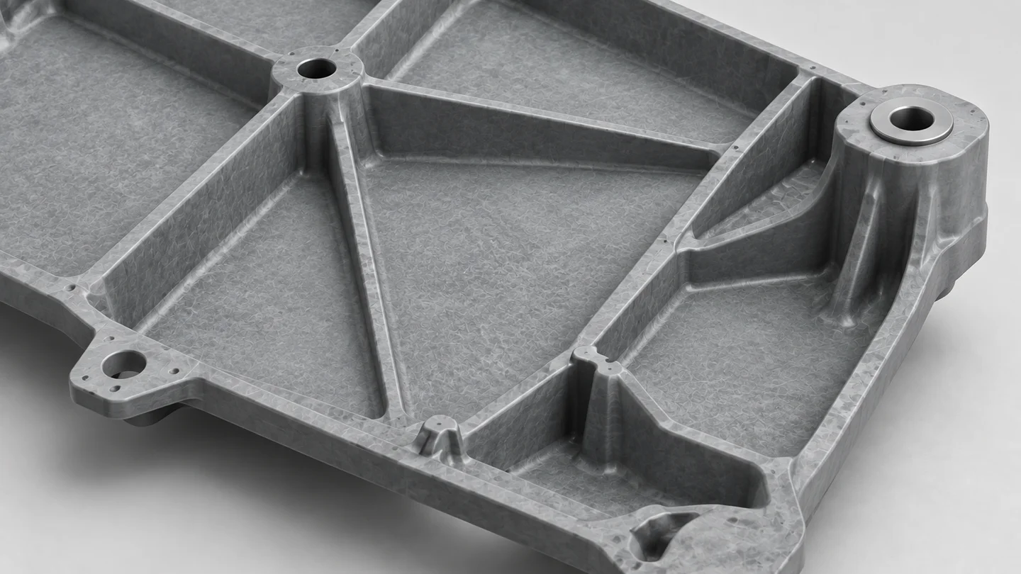
Keep each sample linked to its forming conditions. Record which charge layout produced each sample and assess the regions identified at the start. Where direction-dependent behaviour matters, the test plan should address that question rather than relying only on a generic material data sheet.
Component testing also needs representative supports and load application. Otherwise, a fixture difference can be mistaken for a change in the part. The responsible engineers should select the material characterisation, analysis and component tests needed for the agreed acceptance requirements.
For SUASE, the tooling discussion can then focus on a concrete decision: retain the proposed geometry, change a local feature, or investigate the forming conditions further before committing to a modification. That keeps mould decisions connected to the evidence needed for the finished component.
If a D-LFT part is under development, contact SUASE with an existing drawing marked with its main supports and load direction. That is enough to begin discussing which tooling questions need attention first.