
A compression mold is not simply a machined cavity used to shape composite material. For SMC, BMC, GMT, LFT, CF-SMC and other compression molding processes, the tooling must control material flow, temperature, pressure, dimensional accuracy, venting, demolding and production repeatability at the same time.
This is why the quality of a compression mold depends on much more than CNC machining accuracy. The engineering decisions made before steel is cut can determine whether the final tool runs reliably for years or requires repeated modifications during production.
For buyers, this also explains why choosing a compression mold manufacturer should not be based only on quotation price or machining capacity. A capable supplier must be able to translate product requirements into a complete tooling solution.
What Does a Compression Mold Manufacturer Actually Deliver?
When a customer sends a product drawing to a tooling supplier, the expected deliverable is not merely a pair of mold halves. A production-ready compression mold normally involves several engineering systems working together.
- Product and manufacturability analysis
- Compression mold design
- Cavity and core development
- Parting and sealing strategy
- Material flow considerations
- Heating or cooling system design
- Venting strategy
- Ejection and demolding design
- Guide and alignment system
- Precision machining
- Mold assembly and fitting
- Trial molding and process adjustment
- Dimensional and functional inspection
The important point is that these activities are interconnected. A change in product geometry may affect the parting line. The parting line can affect venting and flash control. Rib geometry can influence material flow and local temperature. The final mold structure must therefore be developed as an integrated system.
Step 1: Start with the Product, Not the Mold
Professional compression mold design begins with understanding the molded component.
Before creating the detailed tooling structure, engineers should review:
- 3D product geometry
- 2D drawings and dimensional tolerances
- Material type
- Material shrinkage characteristics
- Wall thickness distribution
- Ribs and bosses
- Mounting points
- Insert requirements
- Surface quality requirements
- Annual production volume
- Available press capacity
This initial review is essentially a tooling-oriented DFM process. Its purpose is to identify problems while they are still inexpensive to change.
A product that looks acceptable from a design perspective may still be difficult to compression mold because of insufficient draft, unfavorable material flow, inaccessible surfaces, excessive local thickness or unsuitable trimming geometry.
Why DFM Is the First Test of a Compression Mold Supplier
One of the clearest differences between a machining-oriented supplier and an experienced compression mold manufacturer is the quality of the DFM review.
A supplier that immediately starts modeling the mold without challenging the product design may simply transfer manufacturing problems into the tooling.
A professional DFM review asks questions such as:
- Can the part be released from the mold reliably?
- Where should the parting line be located?
- Will the material reach thin or deep areas effectively?
- Where should vents be positioned?
- Can the proposed ribs be machined and polished?
- Will local features create excessive stress concentration?
- Is the proposed trimming edge suitable for production?
- Can the mold be maintained after thousands of cycles?
Resolving these questions before manufacturing begins can significantly reduce engineering changes during mold trials.
Step 2: Define the Compression Mold Architecture
After the product has passed the feasibility review, the next task is to define the overall mold architecture.
Depending on the component, the tooling may include:
- Upper mold
- Lower mold
- Cavity and core inserts
- Replaceable wear components
- Guide systems
- Ejection mechanisms
- Heating components
- Cooling components where required
- Vacuum or venting systems
- Hydraulic or mechanical auxiliary actions
The architecture should reflect both the geometry of the product and the expected production environment.
A prototype tool and a high-volume production mold may require different solutions even when they manufacture the same component. Production volume influences component durability, replaceability, maintenance access and automation requirements.
Step 3: Select the Right Mold Steel and Surface Strategy
Mold steel selection is another important part of compression tooling engineering. The appropriate grade depends on the material being molded, production volume, temperature, wear conditions, surface requirements and machining strategy.
SMC and BMC contain glass fibers and mineral fillers that can contribute to abrasive wear. A mold intended for long-term production therefore needs sufficient hardness, toughness and dimensional stability.
The surface treatment may also be selected according to the application. Depending on the mold and production requirements, options can include:
- Polishing
- Texturing
- Chrome plating
- Nitriding
- Other wear-resistant surface treatments
The objective is not to select the hardest possible material. The tooling system should instead achieve the required combination of machinability, durability, surface quality and service life.
Step 4: Engineer the Mold for Material Flow
Compression molding differs from conventional machining because the mold must accommodate a material that changes its behavior during the molding cycle.
Before curing, SMC and other thermoset compounds must flow and fill the cavity. During the process, viscosity, temperature and curing state change continuously.
This creates an important design relationship:
Charge placement → material flow → pressure distribution → fiber distribution → curing → final part quality.
The mold designer therefore needs to understand how the charge is expected to move through the cavity rather than treating the cavity as a simple negative image of the finished part.
Step 5: Design for Controlled Flash
Flash is one of the most visible indicators of compression molding performance. Excessive flash increases trimming work and can also indicate problems with mold closure, material distribution or parting-line design.
Flash control depends on several elements working together:
- Parting-line location
- Shear-edge geometry
- Mold clearance
- Material charge control
- Press alignment
- Clamping force
- Mold wear resistance
A well-engineered compression mold does not attempt to eliminate every gram of overflow through excessive mechanical force. Instead, it establishes a controlled material boundary and allows the process to operate consistently.
Step 6: Integrate the Heating System into the Mold Design
For thermoset compression molding, the mold is also a thermal processing system.
Heat must be transferred from the mold into the material consistently enough to support predictable curing. Large temperature differences across the cavity can create differences in cure behavior, shrinkage and dimensional stability.
Depending on the application, the mold may use:
- Thermal oil heating
- Electric cartridge heaters
- Steam or other heating methods
- Multiple independently controlled heating zones
Heating-channel layout should be considered during the structural design stage. Adding a heating system after the main mold structure has already been finalized can limit the available thermal design options.

Step 7: Design Venting and Gas Evacuation
During compression molding, air and process gases must escape from the cavity. If they remain trapped, defects such as voids, surface imperfections, incomplete filling or local quality variation may occur.
Venting must therefore be designed according to the expected material flow.
Poor vent design can create two opposite problems:
- Insufficient venting can trap gas inside the cavity.
- Excessive or poorly controlled venting can create additional material leakage paths.
The best solution is a controlled venting network that supports gas evacuation without unnecessarily increasing flash.
Step 8: Design the Mold for Demolding and Maintenance
A compression mold should not only produce the first acceptable part. It should also release the part consistently after repeated production cycles.
Demolding design may involve:
- Draft angles
- Ejector systems
- Mechanical lifters
- Hydraulic or pneumatic assistance
- Replaceable inserts
- Accessible maintenance areas
Maintenance should also be considered during the original mold design. Components that experience high wear should be replaceable without rebuilding the entire tooling structure.
Step 9: Precision Machining Is Only Part of Mold Manufacturing
Once the design has been released, the compression mold factory begins manufacturing the tooling. CNC machining provides the geometric foundation, but machining alone does not determine the final performance of the mold.
A typical manufacturing sequence may include:
- Steel preparation and material inspection
- Rough machining
- Heat treatment where required
- Finish CNC machining
- EDM or other secondary processing
- Drilling and auxiliary feature machining
- Surface treatment or finishing
- Manual fitting
- Assembly
- Dimensional inspection
Large or complex compression molds may require high-accuracy machining and coordinated inspection to maintain the relationship between multiple tooling components.
Why Mold Assembly and Fitting Matter
Even when individual components meet their drawings, the assembled mold can still have problems if interfaces are not correctly fitted.
Assembly affects:
- Mold closure
- Parting-line contact
- Insert alignment
- Ejection movement
- Guide-system accuracy
- Venting consistency
This is why a professional compression mold manufacturer needs experienced fitting and assembly capability in addition to CNC equipment.
Step 10: Mold Trial Turns the Tool into a Production System
A newly manufactured mold should not be considered production-ready simply because the machining process is complete.
The mold trial is where the engineering assumptions are tested under actual molding conditions.
During a trial, engineers may evaluate:
- Part dimensions
- Surface appearance
- Flash condition
- Material filling
- Venting performance
- Demolding behavior
- Heating uniformity
- Cycle time
- Part-to-mold fit
Trial results may lead to controlled engineering modifications. This is a normal part of compression mold development, especially for complex automotive and structural composite components.
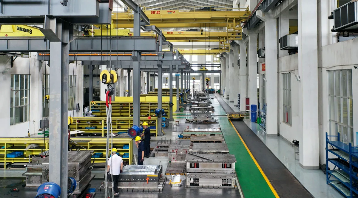
From First Trial to Production-Ready Tooling
The goal of mold trials should not be limited to producing one good sample. The real objective is to establish a repeatable manufacturing window.
A production-ready tool should provide stable results when reasonable variations occur in:
- Material batches
- Charge placement
- Production cycles
- Ambient conditions
- Operator handling
- Normal tooling wear
This distinction is important when evaluating a compression mold supplier. A supplier that can produce a good trial sample is useful; a supplier that can engineer a mold for stable long-term production provides significantly greater value.
How to Evaluate a Compression Mold Factory
When comparing a compression mold factory or manufacturer, buyers should look beyond the number of CNC machines.
| Evaluation Area | What to Check |
|---|---|
| Engineering | DFM capability, material knowledge, mold design experience |
| Design | 3D mold design, flow considerations, thermal and venting strategy |
| Machining | CNC accuracy, large-format machining capability, process control |
| Assembly | Fitting accuracy, alignment, moving components and mold closure |
| Inspection | CMM, dimensional measurement, surface and functional inspection |
| Trial | Actual compression molding capability and engineering adjustment |
| Support | Modification, maintenance and technical support after delivery |
Compression Mold Supplier vs. Compression Mold Manufacturer
The terms compression mold supplier and compression mold manufacturer are often used interchangeably, but they can represent different business models.
A supplier may coordinate tooling production through multiple external resources. A manufacturer with its own engineering, machining, assembly and trial capabilities can maintain greater control over the complete development process.
For complex tooling, this difference can become important when engineering changes are required.
When design, machining, assembly and trial are closely connected within one organization, technical feedback can move more quickly from the production floor back to the engineering team.
What Information Should Buyers Provide for a Compression Mold Project?
A detailed RFQ allows the manufacturer to evaluate the tooling more accurately before quotation.
Useful information includes:
- 3D product model
- 2D product drawing
- Material specification
- Material supplier or grade
- Annual production volume
- Available press size
- Required cavity quantity
- Surface finish requirements
- Dimensional tolerance requirements
- Insert requirements
- Automation requirements
- Target cycle time
- Expected tool life
The more complete the technical information, the easier it is for a compression mold manufacturer to optimize the tooling structure before manufacturing begins.
How Professional Compression Mold Design Reduces Total Cost
Tooling cost should be evaluated over the complete production lifecycle rather than only by the initial quotation.
A lower-cost mold may become more expensive if it requires:
- Repeated design modifications
- Long trial periods
- Frequent maintenance
- High trimming requirements
- Unstable dimensional performance
- Short component life
- Production downtime
Conversely, a well-engineered tool can reduce these costs through better manufacturability, stable process conditions and easier maintenance.
This is why compression mold design should be viewed as an investment in production stability rather than simply an engineering drawing exercise.
Why Choose an Integrated Compression Mold Manufacturer?
Complex composite tooling benefits from an integrated workflow in which engineering, manufacturing and validation are connected.
SUASE provides compression tooling development across the complete workflow, including product and DFM evaluation, mold design, precision machining, assembly, trial molding, inspection and production support. Its current engineering system covers SMC, BMC, CF-SMC, PCM, HP-RTM, BAYPREG and thermoplastic composite processes.
For projects involving large automotive components, EV battery enclosure parts, electrical products, sanitary products or other composite structures, an integrated engineering approach can help reduce the gap between the CAD model and the final production process.
Compression Mold Manufacturing: From CAD to Mass Production
The complete development path can be summarized as:
Product Data → DFM → Compression Mold Design → Simulation → Machining → Assembly → Mold Trial → Inspection → Pilot Production → Mass Production
Each stage answers a different engineering question.
| Stage | Primary Engineering Objective |
|---|---|
| Product Review | Determine whether the component can be molded reliably |
| DFM | Identify risks before tooling manufacture |
| Mold Design | Define cavity, structure, heating, venting and ejection systems |
| Machining | Convert the design into accurate physical components |
| Assembly | Establish accurate interfaces and mold movement |
| Trial | Validate actual molding performance |
| Inspection | Confirm dimensional and functional requirements |
| Pilot Production | Verify repeatability under realistic production conditions |
Conclusion
A high-quality compression mold is the result of engineering decisions made across the entire tooling lifecycle. The quality of the final product depends not only on machining precision, but also on DFM analysis, material behavior, mold architecture, thermal management, venting, alignment, assembly and trial validation.
For buyers looking for a compression mold supplier, compression mold manufacturer or compression mold factory, the most important question is therefore not simply “How much does the mold cost?”
A better question is:
Can the manufacturer turn my product requirements into a stable, maintainable and production-ready compression molding system?
That capability is what separates a machining vendor from a long-term tooling engineering partner.
Frequently Asked Questions About Compression Mold Manufacturing
What does a compression mold manufacturer do?
A compression mold manufacturer develops and produces tooling for compression-molded components. Its responsibilities may include DFM analysis, mold design, machining, assembly, mold trials, inspection and production support.
What should I look for in a compression mold supplier?
Important factors include engineering capability, composite material experience, mold design quality, machining capacity, inspection systems, trial molding capability, project management and after-sales technical support.
Why is compression mold design important?
Compression mold design determines how the material flows, how the mold is heated, how gases escape, how the part is released and how accurately the finished component can be produced.
What materials can compression molds be used for?
Compression molds are widely used with materials and processes including SMC, BMC, CF-SMC, GMT, LFT, PCM, thermoset composites and other reinforced polymer systems.
How long does it take to manufacture a compression mold?
The development time depends on product complexity, mold size, cavity structure, material, surface requirements, machining workload and trial requirements. A reliable schedule should be established after reviewing the product data and technical specifications.
Should mold trials be included before final acceptance?
Yes. Mold trials provide an opportunity to verify dimensions, surface quality, flash, material filling, demolding and process stability before the tooling enters regular production.