
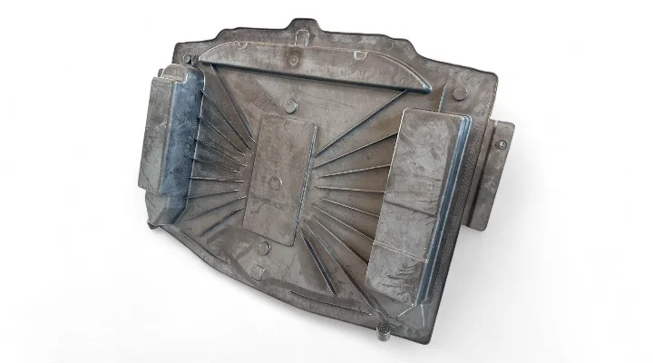
A composite spare wheel well mold is a specialized automotive tooling solution used to manufacture the recessed structure that accommodates a spare wheel or related equipment within a vehicle body. As automotive manufacturers continue to pursue lightweight structures and higher levels of functional integration, composite materials are becoming an option for components traditionally produced from stamped steel or other conventional materials.
The wheel well is not simply a shaped storage cavity. Its geometry can influence packaging, local structural stiffness, water management, dimensional accuracy, and the fit of surrounding body components. For this reason, tooling design must consider both the final component requirements and the characteristics of the selected composite material.
For SMC and other compression molded composites, mold structure, material flow, shrinkage, venting, parting line location, and demolding behavior all have a direct influence on production quality.
What Is a Composite Spare Wheel Well Mold?
A composite spare wheel well mold is a compression molding tool designed to form a composite wheel well component into its required three-dimensional geometry.
Depending on the vehicle platform, the molded component may include:
- A recessed wheel storage area.
- Reinforcing ribs.
- Mounting bosses.
- Fastening features.
- Drainage openings.
- Interfaces with surrounding body panels.
- Local structural reinforcement.
The mold must reproduce these features consistently while maintaining dimensional stability throughout repeated production cycles.
Why Use Composite Materials for Spare Wheel Wells?
Traditional wheel well structures can be manufactured from formed metal, but composite materials provide opportunities for weight reduction and functional integration.
Depending on the selected material system and design, composites can offer:
- Lower component weight.
- Good stiffness-to-weight performance.
- Corrosion resistance.
- Complex molded geometry.
- Integrated ribs and mounting features.
- Good dimensional repeatability.
These characteristics make composite wheel well structures particularly interesting for lightweight vehicle development and electric vehicle platforms.
SMC for Composite Spare Wheel Well Components
SMC is a practical material for producing automotive composite components in relatively high production volumes. The material can be compression molded into deep or curved geometries while integrating multiple structural features into a single component.
For a spare wheel well application, the SMC formulation and reinforcement architecture should be selected according to the required stiffness, impact resistance, temperature performance, and dimensional stability.
The compression molding process can also reduce the number of secondary assembly operations by incorporating features directly into the molded part.
Key Design Requirements for a Spare Wheel Well Mold
Deep and Curved Geometry
A wheel well commonly contains a deep recessed area with curved transitions. These areas require careful consideration during mold design because material flow can become more difficult around corners, deep sections, and changes in wall geometry.
Smooth transitions and appropriate radii can help improve material distribution and reduce localized stress concentrations.
Dimensional Accuracy
The finished wheel well must fit accurately within the vehicle body structure. Dimensional variation can create problems during assembly, particularly around mounting points and interfaces with adjacent components.
The mold therefore needs to maintain stable cavity geometry during repeated heating, cooling, and compression cycles.
Local Reinforcement
Mounting points and fastening areas may experience higher loads than the main panel surface. These regions may require increased material thickness, ribs, bosses, or other reinforcement features.
Material Flow and Charge Layout
Material placement is an important factor in the development of a compression mold for a composite wheel well.
The initial SMC charge should be positioned according to the geometry and expected flow behavior of the component. Poor charge placement may result in:
- Incomplete filling.
- Uneven fiber distribution.
- Weld lines.
- Air entrapment.
- Local thickness variation.
- Surface defects.
Mold engineers should therefore evaluate material flow during the design stage and optimize the charge layout where necessary.
Parting Line Design
Parting line design is particularly important for large automotive composite components.
An effective parting line should provide reliable mold closing, controlled flash, efficient venting, and practical demolding.
For a spare wheel well mold, engineers should avoid unnecessary parting surfaces in critical appearance or sealing areas whenever possible.
The parting surface also needs sufficient machining accuracy to maintain consistent contact between the mold halves during compression.
Venting Design for Composite Wheel Well Molds
Air and gases trapped inside a mold cavity can cause defects if they cannot escape efficiently during compression molding.
Typical defects associated with inadequate venting include:
- Voids.
- Burn marks.
- Surface imperfections.
- Incomplete filling.
- Local porosity.
Venting can often be incorporated around suitable cavity boundaries and parting surfaces. The venting design must balance effective gas evacuation with flash control.
Shrinkage Compensation in Composite Wheel Well Tooling
Composite materials experience dimensional changes during curing and cooling. SMC molding therefore requires appropriate shrinkage compensation when determining the final mold cavity dimensions.
Shrinkage behavior is affected by several factors, including:
- Material formulation.
- Fiber content.
- Molding temperature.
- Part geometry.
- Wall thickness.
- Processing conditions.
Incorrect shrinkage allowance can result in dimensional deviation and difficulties during vehicle assembly. The tooling design should therefore be based on the actual material and process conditions rather than relying only on generic shrinkage values.
Mold Temperature Control
Temperature control has a direct influence on SMC curing and dimensional stability.
For a large composite wheel well mold, uneven temperature distribution can cause differences in curing behavior and local dimensional variation.
The heating system should therefore be designed to provide stable and relatively uniform temperature distribution across the working surfaces.
Important considerations include:
- Heating zone arrangement.
- Temperature sensor locations.
- Heat transfer efficiency.
- Mold thickness.
- Thermal balance between upper and lower mold halves.
Demolding Considerations
The deep geometry of a wheel well can make demolding more challenging than that of a relatively flat composite panel.
The mold design should consider:
- Draft angles.
- Deep cavity geometry.
- Potential undercuts.
- Part shrinkage.
- Release behavior.
- Part handling after molding.
Where the product geometry permits, suitable draft angles and smooth transitions can simplify demolding and reduce the risk of damaging the molded component.
Mold Rigidity and Structural Stability
Automotive wheel well molds can be relatively large and may experience substantial compression forces during production.
Insufficient mold rigidity can lead to:
- Parting surface deformation.
- Uneven flash.
- Dimensional variation.
- Premature tooling wear.
- Inconsistent product quality.
The mold base and supporting structure should therefore be designed to maintain cavity geometry under actual molding loads.
CNC Machining and Mold Accuracy
Precision machining is essential for producing composite automotive tooling with stable dimensional performance.
CNC machining can be used to manufacture complex cavity surfaces, ribs, bosses, and other geometric details with controlled tolerances.
After machining, critical areas should be inspected to verify:
- Cavity dimensions.
- Parting surface accuracy.
- Mounting locations.
- Reference points.
- Surface finish.
Accurate machining provides a reliable foundation for subsequent mold assembly and trial production.
Mold Trial and Validation
A composite spare wheel well mold should be validated through practical mold trials before final production approval.
During a trial, engineers can evaluate:
- Material filling.
- Flash distribution.
- Surface quality.
- Dimensional accuracy.
- Demolding behavior.
- Mounting feature accuracy.
Trial results can be compared with product drawings and inspection data to identify areas requiring tooling or process adjustments.
Quality Control for Composite Spare Wheel Well Molds
Tooling quality directly influences the consistency of the molded component. A professional quality control process should therefore cover both individual components and the completed mold assembly.
Typical inspection activities include:
- Raw material verification.
- CNC machining inspection.
- Dimensional measurement.
- Parting surface inspection.
- Mold assembly verification.
- Trial part inspection.
- Final tooling acceptance.
For automotive projects, inspection documentation can also help customers track dimensional results and confirm compliance with project requirements.
Composite Spare Wheel Well Mold for Electric Vehicles
Electric vehicle manufacturers are placing greater emphasis on vehicle lightweighting and efficient packaging. A composite spare wheel well can be considered as one component within a broader lightweight vehicle structure.
Depending on the vehicle architecture, the area may be used for spare wheel storage, tools, charging equipment, cables, or other components.
Composite construction can provide designers with greater flexibility when integrating these functions into a molded structure.
Common Challenges in Composite Wheel Well Mold Development
Several technical challenges should be addressed during tooling development.
Complex Geometry
Deep recesses, curved surfaces, ribs, and mounting features can make material flow and demolding more difficult.
Dimensional Stability
Large composite components can experience dimensional variation caused by material shrinkage, temperature gradients, and structural deformation.
Flash Control
High compression pressure can force material toward the parting surface. Accurate tooling and suitable process parameters are necessary to control flash.
Production Repeatability
A successful tooling design must maintain stable performance over repeated molding cycles rather than producing only a successful first trial part.
How SUASE Approaches Composite Automotive Tooling
At SUASE, composite tooling is developed with attention to both mold manufacturing and the actual production requirements of the finished component.
For automotive compression molds, the engineering process can include:
- Product and drawing review.
- DFM analysis.
- Parting line development.
- Material flow considerations.
- Shrinkage compensation.
- Venting design.
- Heating system planning.
- Precision CNC machining.
- Mold assembly.
- Trial production and optimization.
This integrated approach helps reduce tooling modification risks and supports stable production of complex composite automotive components.
Conclusion
A composite spare wheel well mold requires careful engineering because the component combines complex geometry, dimensional requirements, structural features, and automotive production demands.
For SMC and other compression molded materials, successful tooling depends on coordinated control of material flow, shrinkage, parting line design, venting, temperature, mold rigidity, and demolding.
As vehicle manufacturers continue to explore lightweight composite structures, well-engineered tooling will remain essential for converting complex product designs into stable, repeatable production components.
SUASE provides compression mold and composite tooling solutions for automotive and industrial applications, supporting customers from mold design and manufacturing through trial validation and production optimization.
Frequently Asked Questions About Composite Spare Wheel Well Molds
What is a composite spare wheel well mold?
It is a specialized mold used to compression mold composite materials into the recessed wheel well structure used in automotive applications.
What materials can be used for a composite spare wheel well?
SMC and other fiber-reinforced polymer systems can be considered depending on the required stiffness, weight, impact resistance, dimensional stability, and production volume.
Why is venting important in a wheel well mold?
Effective venting allows trapped air and curing gases to escape during molding, helping reduce voids, burn marks, and surface defects.
Why is shrinkage allowance important?
Composite materials change dimensions during curing and cooling. Correct shrinkage compensation helps the finished wheel well meet its required dimensions and fit surrounding vehicle structures.
What should be considered when designing a spare wheel well mold?
Important factors include product geometry, material flow, parting line design, venting, shrinkage, temperature control, mold rigidity, demolding, and dimensional inspection.