
An SMC shower tray must do more than achieve the required external shape. Its molded surface must support effective water drainage, its drain opening must align with the plumbing interface, and its perimeter must fit the intended installation. Surface appearance, dimensional stability and repeatable production quality are equally important for sanitary ware manufacturers.
These requirements begin with the tooling. A well-designed SMC shower tray mold must translate product geometry into a manufacturable compression molding process while accounting for material behavior, mold temperature, part release, surface finishing and inspection.
This article explains the engineering considerations that matter when developing a shower tray compression mold, with a focus on drainage geometry, drain alignment, surface quality and dimensional verification. It is intended for sanitary ware manufacturers, product engineers, tooling buyers and procurement teams evaluating a shower tray mold manufacturer or supplier.
SUASE SMC Shower Tray Mold Engineering & Performance Matrix
SMC shower tray mold engineering requires coordinated control of drainage geometry, surface texture, thermal behavior, flash formation and structural features. The following matrix summarizes common manufacturing challenges, potential tooling countermeasures and the verification methods that can be defined for each project.
| Design Pillar | SMC Shower Tray Manufacturing Challenge | Potential SUASE Tooling Solutions | Recommended Verification |
|---|---|---|---|
| Drainage Slope and Drain Alignment | Inadequate drainage geometry may cause localized water retention. Poorly designed drain interfaces can also create dimensional, sealing or local structural problems. | CNC-machined drainage profiles, coordinated slope transitions, accurately located drain openings and an engineered local cavity structure around the drain interface. Slope values and local reinforcement should be determined from the product specification and engineering review. | Inspect the finished floor profile, drain position and critical dimensions. Conduct a drainage assessment using the agreed product and installation conditions. |
| Surface Finish and Texture | Inconsistent texture replication, surface marks, pinholes or unsuitable transitions between textured and smooth areas can affect appearance and cleaning. | Define separate finishing requirements for visible smooth surfaces and textured regions. Evaluate suitable polishing, texturing or surface-treatment methods according to the product appearance specification and mold material. | Inspect surface appearance, texture consistency and specified visible areas against approved reference samples or documented acceptance criteria. |
| Thermal Balance and Flatness | Temperature variation, material behavior and cooling conditions may contribute to dimensional variation or warpage in large molded components. | Review the heating layout, temperature-control strategy, mold structure and process conditions. Where appropriate, evaluate multi-circuit heating arrangements and temperature-monitoring points for the specific tool. | Record temperatures at defined locations under specified operating conditions. Measure finished-part flatness and critical dimensions after molding. |
| Shear Edge and Flash Control | Excessive flash, inconsistent edge trimming or fiber pull-out can increase finishing work and affect edge appearance. | Review parting-line geometry, shut-off design, shear-edge configuration, mold alignment and process conditions. Define critical edge requirements according to the material and product geometry. | Inspect flash thickness and edge quality on trial parts. Record recurring defects and verify corrective actions during subsequent trials. |
| Rib Design and Structural Rigidity | Inadequate local stiffness or poorly designed rib transitions may contribute to excessive deflection, cracking, noise or difficult demolding. | Evaluate rib layout, section transitions, corner radii and draft angles in relation to the intended load cases, material behavior and release direction. | Inspect molded rib geometry and critical dimensions. Where required, perform agreed load, deflection and demolding assessments. |
Engineering note: Specific values for drainage slope, mold temperature uniformity, shear-edge clearance, steel grade, surface treatment and rib draft must be confirmed against the approved design, selected SMC material, tooling requirements and validation results. They should not be treated as universal specifications for every shower tray mold.
An SMC shower tray mold manufacturer should control five critical areas: drainage geometry, drain-interface accuracy, surface finish, thermal stability and flash-free edge formation. Each area should be linked to a defined design requirement and a measurable finished-part acceptance criterion.
1. Why Shower Tray Mold Design Requires Application-Specific Engineering
Shower trays are available in different shapes, sizes, installation styles and surface designs. A rectangular tray, a quadrant shower tray and a low-profile shower base can have different drainage paths, perimeter conditions, reinforcement requirements and installation interfaces.
For an SMC compression molding project, the mold must reproduce these features consistently without introducing unacceptable surface defects, dimensional variation or demolding problems.
Key design inputs normally include:
- Overall tray dimensions and installation envelope.
- Drain opening location, diameter and interface requirements.
- Specified drainage geometry and the intended direction of water flow.
- Floor profile, local transitions, corner radii and perimeter geometry.
- Surface finish, texture and appearance requirements.
- Required wall or floor thickness and local structural features.
- Material grade and the intended SMC molding process.
- Production volume, press capability and target cycle time.
- Dimensional inspection criteria and finished-part acceptance requirements.
These requirements should be confirmed before detailed tooling design. A mold that reproduces the nominal CAD geometry may still need engineering adjustments to achieve the required finished-part dimensions and production consistency.
2. Drainage Geometry: Design the Water Path Before Cutting the Mold
Drainage performance is one of the most important functional considerations in shower tray design. The floor profile must guide water toward the drain without creating unintended low spots, persistent puddles or abrupt transitions that interfere with cleaning and use.
2.1 Define the Required Floor Profile
The product design should define the intended drainage direction, slope transitions and relationship between the surrounding floor and the drain opening. These features must be interpreted as a coordinated surface rather than a collection of isolated dimensions.
A tray may include several sloped regions that converge toward a drain. If those regions meet with poorly controlled transitions, the finished surface can develop local depressions or changes in slope that affect water flow.
During mold design, the engineering team should review the complete three-dimensional surface and identify areas where adjacent slopes, corner radii or molded features could create difficult transitions.
2.2 Avoid Local Low Spots and Unintended Ridges
Local low spots can retain water even when the overall tray appears to have the correct slope. Unintended ridges may interrupt the intended water path. Both conditions can result from product geometry, tooling inaccuracies, process variation or dimensional changes during molding and cooling.
Recommended engineering checks include:
- Reviewing the surface profile from the outer perimeter to the drain.
- Checking the continuity of adjoining slope regions.
- Inspecting corners and transitions for local depressions or raised areas.
- Identifying critical surface sections for dimensional measurement.
- Confirming the inspection method for evaluating the finished drainage profile.
The acceptable drainage profile should be defined by the product specification and relevant installation requirements. There is no single slope value that is appropriate for every shower tray design.
2.3 Separate Nominal Geometry from Finished-Part Performance
The mold cavity is based on the intended product geometry, but the finished SMC component may respond to molding conditions, material shrinkage and cooling behavior. The relationship between nominal tool geometry and actual part geometry therefore needs to be evaluated during tooling development.
Where inspection reveals a drainage problem, engineers should determine whether the cause lies in the original surface design, tool machining, process conditions or finished-part dimensional variation before making corrective changes.
3. Drain Opening Alignment and Plumbing Interface Control
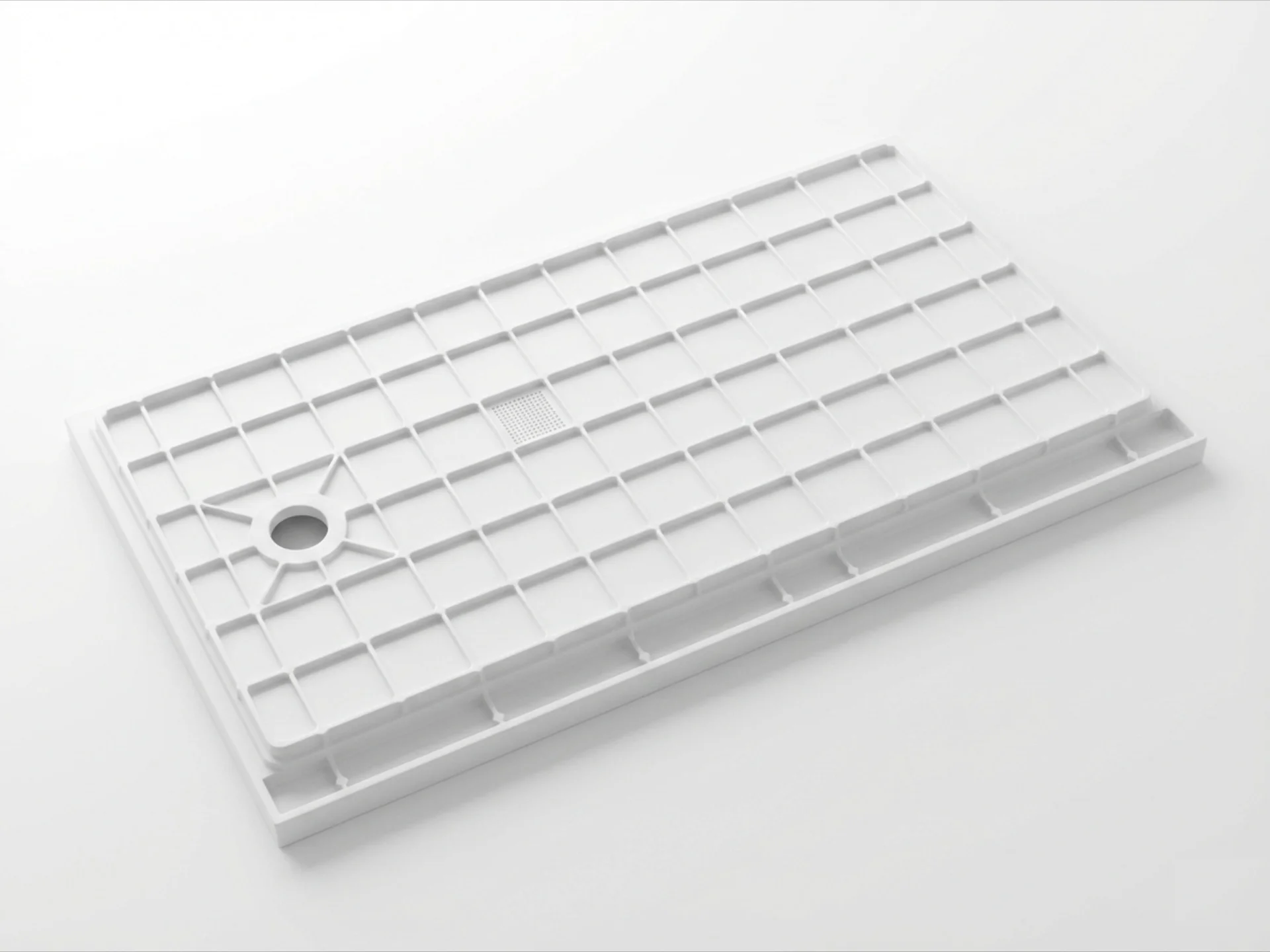
Drainage performance depends not only on the floor profile but also on the relationship between the molded drain opening and the intended plumbing assembly.
An opening that is positioned incorrectly, has an unsuitable edge profile or varies beyond the specified tolerance can complicate installation. Depending on the drain design, the surrounding sealing surface and mounting interface may also be critical.
3.1 Establish the Correct Datum System
The drain opening should be located relative to clearly defined product datums. Using consistent datums allows the mold designer, machinist and quality team to interpret the same nominal position and measure the finished part consistently.
Important controls may include the distance from reference edges, opening diameter, local surface profile and the position of any related mounting or sealing features.
3.2 Review the Drain Interface as an Assembly
Drainage hardware should be considered during product and mold design rather than after the tray geometry has been finalized. The review should account for the intended drain fitting, available installation space, sealing method and access needed for assembly.
Where the drain interface includes a flat sealing region, that region may require specific dimensional and surface requirements. These should be defined according to the selected hardware and the customer's assembly specification.
3.3 Verify Alignment on the Finished Component
Mold inspection confirms tool geometry, but finished-part inspection confirms whether the molded component meets the product requirements. A suitable inspection plan should verify drain location and critical dimensions after molding.
If the tray is supplied to a plumbing or sanitary ware assembly manufacturer, a representative fit check may provide additional evidence that the interface works as intended.
4. Surface Quality: Prevent Waviness, Pinholes and Visible Defects
Surface quality is a major consideration for sanitary ware tooling. A shower tray may have a large visible area where waviness, pinholes, scratches or inconsistent texture can affect customer acceptance.
These defects should not automatically be attributed to the mold alone. Their causes can include the molded material, material handling, surface preparation, process conditions, tool condition or post-molding operations.
4.1 Define the Required Surface Finish
Before tooling begins, the customer and mold manufacturer should agree on the intended surface appearance. Depending on the product, requirements may include a smooth visible surface, a specified texture, defined gloss characteristics or localized surface treatments.
The inspection standard should identify which surfaces are visible, which defects are unacceptable and how the finished part will be evaluated. Visual standards and approved reference samples can help reduce subjective differences during acceptance.
4.2 Match Mold Finishing to Product Requirements
Mold polishing and surface finishing should follow the required product appearance and the selected molding process. The objective is not simply to make every cavity surface as reflective as possible, but to achieve the specified finish consistently across the relevant product areas.
Areas with complex curvature, deep recesses or narrow transitions may require particular attention during machining and polishing. Tool accessibility and the ability to inspect these areas should be considered during the design stage.
For suitable tooling projects, SUASE provides mold surface finishing and chrome-plating capabilities. Learn more on the SUASE Surface Finishing page.
4.3 Distinguish Tool Marks from Molding Defects
A repeatable surface mark at the same location on multiple parts may indicate a tooling or process-related issue. A defect that changes between cycles may have a different cause, such as material distribution, process variation or inconsistent handling.
Defect analysis should compare the location, shape and repeatability of the affected area. This makes it easier to determine whether the appropriate corrective action involves tool finishing, geometry changes, process adjustment or material control.
5. Anti-Slip Texture and Surface Pattern Replication
Some shower tray designs use molded surface textures to support product appearance and underfoot characteristics. Texture geometry can also affect mold filling, local surface quality, cleaning and the release of the finished part.
5.1 Confirm Texture Requirements Early
The product specification should identify the required pattern, texture boundaries, orientation and any restrictions around the drain or perimeter. These details should be incorporated into the CAD model and reviewed for manufacturability.
5.2 Consider Texture Depth and Mold Release
Deep or sharply defined features may be more difficult to release than shallow, well-radiused textures. The appropriate geometry depends on the material system, mold configuration and part-release method.
Texture design should therefore balance appearance, intended surface function, manufacturability and repeatable demolding. The actual slip-resistance performance, where claimed or required, should be verified using the relevant product test method rather than inferred from texture appearance alone.
5.3 Inspect Pattern Consistency
Texture acceptance should consider whether the pattern is complete and consistent across the designated surface. Localized damage, incomplete replication or visible differences between production parts may indicate a tooling, material or process issue.
6. Perimeter Geometry, Wall Transitions and Installation Fit
A shower tray must fit its intended installation environment. The perimeter, raised edges, wall transitions and underside support areas can affect alignment, stability and the ease of installation.
6.1 Control Critical Dimensions
Overall length and width are important, but they do not fully describe the fit of a molded tray. Perimeter profile, corner geometry, local height, drain position and underside features may also determine whether the product fits the intended installation.
Critical dimensions should be identified in the product drawing and linked to a practical inspection method. Where necessary, a checking fixture can be used to verify several interfaces in a repeatable setup.
6.2 Review Thickness Transitions
Abrupt changes in section thickness can influence material behavior, local stiffness and dimensional consistency. Where the product design permits, smooth transitions and suitable radii can improve manufacturability and reduce stress concentrations.
The final design must also account for any structural or installation requirements imposed by the intended shower tray application.
6.3 Consider Support and Installation Conditions
The underside geometry and the intended support arrangement should be considered together. If the tray relies on specific support locations, these conditions may influence local stiffness and the way installation loads are transferred.
Installation requirements should be provided to the mold manufacturer so that the tooling and product geometry can be reviewed against the actual application.
7. SMC Compression Mold Structure and Material Considerations
SMC compression molding uses a prepared sheet molding compound that is shaped in a heated mold under pressure. For shower tray applications, tooling design must account for the product geometry, material behavior, press capability and required surface quality.
7.1 Select the Tooling Configuration for the Part
The mold configuration should suit the tray's size, geometry, parting strategy, required features and production process. Tooling decisions should also consider access for machining, maintenance and inspection.
7.2 Review Heating and Temperature Uniformity
Stable and appropriate mold temperature is important for repeatable molding. Temperature variation across a large tool can contribute to differences in material cure, surface appearance or finished-part dimensions.
Heating layout and control should be evaluated against the mold geometry, the selected material system and the intended production cycle. The required operating conditions should be established through material guidance and process validation rather than assumed from a generic temperature value.
7.3 Plan for Part Release and Mold Maintenance
The mold must allow the finished tray to be released without unacceptable damage to the visible surface, edges or functional features. Draft, surface condition, parting arrangement and handling access should be reviewed as part of the design.
Maintenance planning should cover cleaning, inspection of critical surfaces, protection of finished areas and any surface treatment used on the mold. Consistent maintenance helps preserve the tool condition required for repeatable production.
8. Dimensional Stability: Connect CAD, Tooling and Finished-Part Inspection
A dimensionally accurate mold is essential, but mold accuracy alone does not guarantee that every finished SMC shower tray will meet its drawing requirements. Material behavior, molding conditions, cooling and measurement conditions can all affect the result.
8.1 Identify Critical-to-Quality Features
The engineering team should identify which dimensions directly affect drainage, drain installation, perimeter fit and product appearance. These features should receive appropriate attention during design review, tool inspection and part validation.
8.2 Use Consistent Measurement Datums
The same datum strategy should be used when reviewing the CAD model, inspecting the mold and measuring the finished component wherever practical. Consistent datums help prevent disagreements caused by different measurement setups.
8.3 Compare Tool Results with Molded Parts
During trial molding, compare measured part dimensions with the product drawing and relevant tool dimensions. If deviations occur, determine whether they are caused by the tool, the process, the material or the inspection setup before applying corrections.
Any compensation introduced into the mold should be documented and verified through subsequent measurements. This creates a traceable link between the original design, tooling modifications and the approved finished part.
9. Shower Tray Mold Trial: What Should Be Verified?
A mold trial is an opportunity to verify whether the tool can produce a part that meets the agreed requirements under defined molding conditions. The acceptance process should evaluate the finished product rather than rely only on the appearance of the mold.
| Verification Area | What to Check | Evidence or Method |
|---|---|---|
| Drainage geometry | Floor profile, slope transitions, local low spots and the relationship between the floor and drain. | Dimensional inspection and an agreed drainage assessment. |
| Drain interface | Opening position, diameter, local surface condition and compatibility with the specified fitting. | Dimensional checks and a representative assembly or fit check. |
| Surface appearance | Waviness, pinholes, scratches, texture consistency and other specified visible defects. | Visual inspection against approved appearance criteria. |
| Overall dimensions | Length, width, perimeter profile, critical heights and installation interfaces. | Measurement against the approved drawing and datum scheme. |
| Part release | Damage, sticking, surface marks or deformation associated with demolding. | Inspection of trial parts and review of the release process. |
| Process repeatability | Variation in key features across representative trial parts. | Recorded process conditions and dimensional or appearance comparisons. |
The final acceptance criteria should be agreed before the trial. Not every project requires the same tests, and any drainage, sealing or performance claim should be assessed using an appropriate method for the intended product.
10. Common SMC Shower Tray Mold Problems and Engineering Responses
Problem 1: Water Remains in Localized Areas
Possible causes: Local changes in the floor profile, dimensional variation, incorrect slope transitions or deformation of the finished part.
Engineering response: Map the affected area, inspect the finished surface and compare the measured geometry with the approved design. Determine whether a product-design change, tooling correction or process adjustment is appropriate.
Problem 2: The Drain Opening Does Not Align with the Fitting
Possible causes: Incorrect datum interpretation, tool machining deviation, dimensional variation or differences between the specified fitting and the actual assembly.
Engineering response: Verify the drawing revision, measurement datums, opening dimensions and fitting requirements. Correct the root cause rather than moving the opening without evaluating the surrounding geometry.
Problem 3: Surface Waviness or Pinholes Appear
Possible causes: Mold surface condition, material behavior, contamination, process inconsistency or unsuitable handling and finishing practices.
Engineering response: Determine whether the defect is repeatable and where it occurs. Inspect the corresponding mold area and review the molding process before deciding on polishing, tooling repair or process changes.
Problem 4: The Finished Tray Is Difficult to Release
Possible causes: Inadequate release geometry, unsuitable surface condition, local undercuts or process conditions that make release inconsistent.
Engineering response: Review the release direction, draft where applicable, local geometry and mold surface condition. Confirm that any change remains compatible with the required product appearance and function.
Problem 5: Critical Dimensions Vary Between Trial Parts
Possible causes: Variable process conditions, inconsistent material behavior, thermal variation, measurement differences or insufficiently controlled tooling interfaces.
Engineering response: Record trial conditions, repeat measurements using a consistent datum scheme and compare the affected features across parts. Correct the underlying source of variation before confirming acceptance.
11. How to Select an SMC Shower Tray Mold Manufacturer
Choosing an SMC shower tray mold manufacturer involves more than comparing the initial tooling quotation. Buyers should assess whether the supplier can understand the sanitary product requirements, manufacture the required tooling and support validation of the finished part.
11.1 Sanitary Ware Tooling Experience
Ask whether the manufacturer has experience with the relevant shower tray geometry, surface finish and production process. Experience with sanitary ware can be particularly useful when the project requires control of large visible surfaces, drain interfaces and complex floor profiles.
11.2 Engineering and Manufacturing Capability
Evaluate the supplier's ability to review CAD data, assess tool design, machine critical surfaces and manage tooling assembly. The supplier should also be able to explain how design requirements will be translated into measurable acceptance criteria.
11.3 Surface Finishing and Tool Protection
Surface quality should be addressed through the full tooling process, including machining, polishing, any specified surface treatment and inspection. Buyers should clarify which finishing operations are performed in-house and how the final condition is checked.
11.4 Trial and Dimensional Validation
Confirm how the manufacturer will verify the tool and finished component, record deviations, manage corrective actions and approve the final configuration. A documented trial process is more useful than a general promise of precision.
11.5 Production and Maintenance Support
Discuss maintenance access, replacement parts, cleaning requirements, surface protection and support after tool delivery. These issues can influence the long-term usability of the mold and the consistency of production.
Learn more about SUASE's mold engineering and manufacturing services through the mold design page, machining page and mold assembly page.
12. What Information Is Needed for a Shower Tray Mold Quotation?
Providing complete project information helps an SMC shower tray mold supplier evaluate the tooling scope, identify engineering risks and prepare a more meaningful quotation.
Where available, include the following information:
- Product CAD data: A 3D model and the latest approved 2D drawing.
- Product dimensions: Overall dimensions, critical tolerances, datum references and perimeter geometry.
- Drain details: Opening position, diameter, fitting model, sealing interface and installation requirements.
- Drainage requirements: Intended water-flow direction, floor profile and any specified acceptance criteria.
- Surface specification: Gloss, texture, visible areas, color requirements and approved appearance samples where available.
- Material information: SMC grade, material supplier and any relevant processing recommendations.
- Production requirements: Expected annual volume, target cycle time and production schedule.
- Press information: Available press dimensions, capacity and other relevant machine constraints.
- Tooling requirements: Preferred mold configuration, applicable standards, maintenance expectations and delivery scope.
- Validation plan: Required dimensional checks, surface acceptance criteria, assembly checks and other specified tests.
If the drainage geometry, material or acceptance criteria are not yet finalized, identify those items as open engineering decisions. This allows the mold manufacturer to clarify assumptions before the tooling design is frozen.
13. SUASE SMC Shower Tray Mold Engineering
SUASE manufactures compression molds for composite applications, including sanitary ware tooling. For shower tray projects, the mold requirements should be evaluated against the product's drainage geometry, surface finish, critical dimensions, selected SMC material and intended production process.
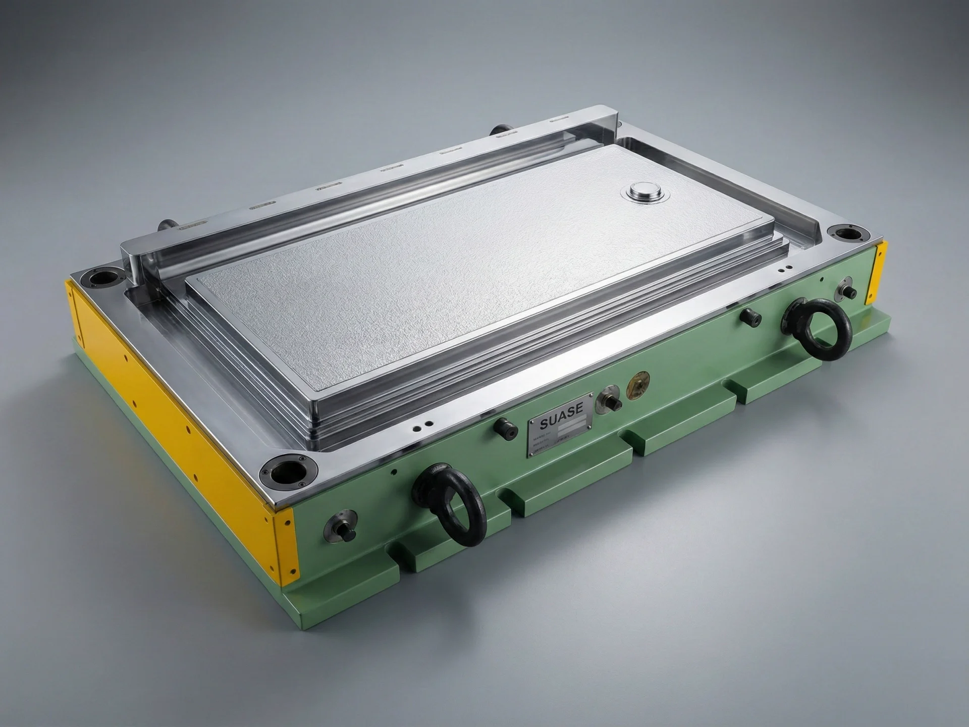
SUASE's published tooling portfolio includes an SMC shower base mold identified as C-25044. The listed project information specifies P20 mold steel, a single cavity, a mold weight of 11.6 tonnes and a 1500-ton press requirement. These details relate to that particular tooling case and should not be interpreted as universal specifications for every shower tray mold.
View the SUASE SMC shower base mold case to review the published project information.
When discussing a new project, buyers should provide the latest product data, drain interface requirements, surface specification, expected production volume and available press information. These inputs allow the engineering team to assess the proposed tooling scope and identify the key design and validation questions.
To discuss a project-specific shower tray compression mold, visit SUASE Contact.
14. Frequently Asked Questions About SMC Shower Tray Molds
What is an SMC shower tray mold?
An SMC shower tray mold is a compression mold used to shape Sheet Molding Compound into a shower tray or shower base. The mold defines the product geometry, including the floor profile, perimeter, drain opening and specified surface features.
Why is drainage geometry important in shower tray mold design?
Drainage geometry determines how the floor guides water toward the drain. Poorly controlled transitions or local depressions can cause water to remain in unintended areas. The finished part should be inspected against the approved geometry and drainage requirements.
How can a shower tray mold help maintain drain alignment?
The design should establish clear datums, control the drain opening relative to those datums and account for the finished-part tolerances. Dimensional inspection and, where appropriate, a representative fitting check help verify that the molded component meets the interface requirements.
What causes surface defects in SMC shower trays?
Possible causes include mold surface condition, material behavior, contamination, inconsistent molding conditions and finishing or handling practices. The defect location and repeatability should be investigated before selecting a corrective action.
Does a polished mold guarantee a defect-free shower tray surface?
No. Mold finishing is important, but the finished surface also depends on material quality, process conditions, tool condition and part handling. Surface acceptance should be verified on molded parts using agreed appearance criteria.
How should anti-slip textures be designed into a shower tray mold?
Texture geometry should be reviewed for pattern consistency, moldability and part release. Any required slip-resistance performance should be verified using the relevant test method rather than assumed from the presence of a molded texture.
What should buyers compare when selecting a shower tray mold supplier?
Buyers should evaluate sanitary ware tooling experience, engineering capability, machining and finishing quality, trial support, dimensional inspection, maintenance planning and the supplier's ability to meet the agreed project requirements.
What information is needed to quote an SMC shower tray mold?
Important inputs include 3D CAD data, 2D drawings, drain specifications, drainage geometry, surface requirements, material information, annual production volume, press constraints and the required validation scope.
Conclusion
SMC shower tray mold design requires coordinated control of drainage geometry, drain alignment, surface finish, perimeter dimensions and part release. These requirements must be translated into practical tooling decisions and verified through inspection of the finished component.
For sanitary ware manufacturers, a capable shower tray mold supplier should be able to review the product design, identify critical interfaces, explain the proposed tooling approach and support a defined validation process.
SUASE supports composite mold development for sanitary ware and other industrial applications. Contact the team to discuss your shower tray drawings, material requirements and production objectives.
Visit SUASE Mould or contact the engineering team to discuss your next SMC shower tray mold project.