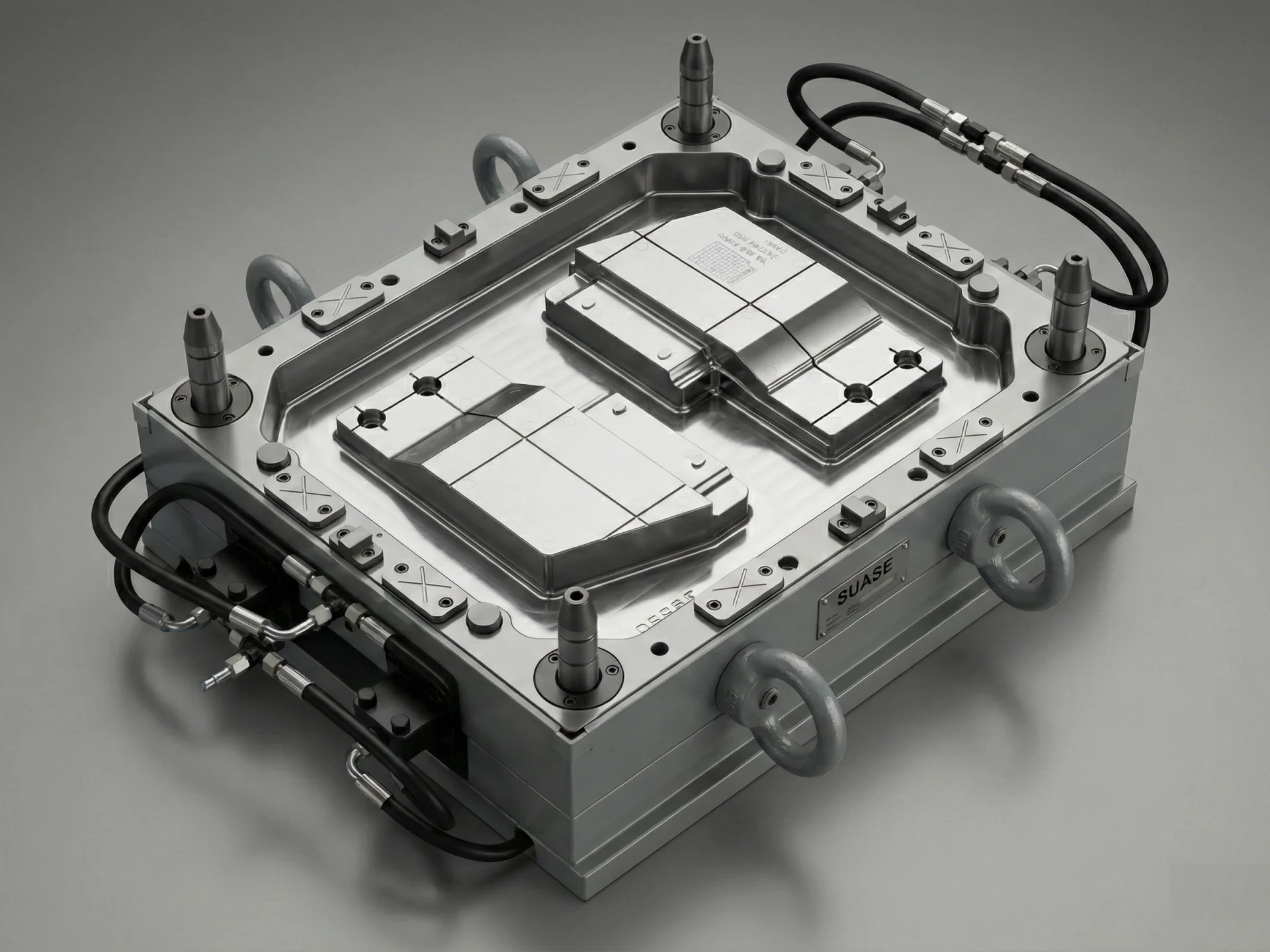
The parting line is one of the most important design elements in an SMC mold. Although it represents only the interface where the mold halves meet, its position and design have a direct influence on product quality, mold durability, production efficiency, and post-processing requirements.
A properly designed parting line helps control material flow, reduces flash, improves venting, simplifies demolding, and minimizes maintenance throughout the mold's service life.
For complex composite components used in automotive, electrical, sanitary ware, and industrial applications, parting line design should be considered during the earliest stages of mold development rather than treated as a final detail.
This article explains the engineering principles of SMC mold parting line design, common design challenges, and practical methods for improving compression mold performance.
What Is a Parting Line in an SMC Mold?
The parting line is the boundary where the upper and lower mold halves separate during opening and closing.
It serves several important functions:
- Defines the mold opening direction.
- Separates cavity and core surfaces.
- Controls flash generation.
- Provides venting locations.
- Supports product demolding.
Unlike many injection molds, SMC compression molds handle highly filled thermoset materials under high pressure. As a result, parting line accuracy becomes even more critical for maintaining dimensional consistency and surface quality.
Why Parting Line Design Matters
An improperly designed parting line may lead to manufacturing problems that affect both product quality and production efficiency.
Potential issues include:
- Excessive flash.
- Uneven cavity filling.
- Air entrapment.
- Difficult demolding.
- Accelerated mold wear.
- Poor surface appearance.
Careful parting line planning helps avoid repeated mold modifications during trial production and contributes to long-term tooling reliability.
Key Principles of SMC Mold Parting Line Design
1. Follow the Natural Geometry of the Product
Whenever possible, the parting line should follow the natural contour of the molded component.
Benefits include:
- Simplified mold machining.
- Improved appearance.
- Reduced visible parting marks.
- Lower finishing requirements.
For exterior automotive panels and decorative composite components, careful positioning of the parting line helps improve final surface quality.
2. Minimize Flash Formation
Flash is one of the most common quality concerns in compression molding. A well-designed parting surface improves sealing between the mold halves and reduces excess material leakage during molding.
Engineers should consider:
- Uniform contact pressure.
- Precision machining.
- Stable mold alignment.
- Adequate mold rigidity.
Effective flash control reduces trimming operations and improves production efficiency.
3. Support Efficient Demolding
The parting line should allow molded parts to be released smoothly without damaging the component or placing excessive stress on ejector systems.
During mold design, engineers evaluate:
- Draft angles.
- Undercut features.
- Part geometry.
- Ejection direction.
Proper demolding design helps shorten production cycles and protects both the mold and the finished component.
Parting Line Design and Flash Control
Flash control is one of the primary objectives of parting line design in compression molding. During the molding cycle, SMC material is compressed under high pressure, and even a slight gap between the mold halves may allow excess material to escape.
Although a small amount of flash is often unavoidable in compression molding, excessive flash increases trimming time, material waste, and production cost.
To improve flash control, mold designers should focus on:
- Maintaining high machining precision on the parting surface.
- Ensuring uniform contact pressure between mold halves.
- Designing sufficient mold rigidity to prevent deformation.
- Using accurate guide pillars and locating components.
- Regular inspection of parting surface wear.
Well-controlled flash not only improves appearance but also helps maintain dimensional consistency throughout long production runs.
Integrating Venting into the Parting Line
Proper venting is another important consideration when designing an SMC mold parting line. During compression molding, trapped air and volatile gases generated during resin curing must be released efficiently.
Without sufficient venting, molded parts may develop defects such as:
- Air pockets.
- Burn marks.
- Incomplete filling.
- Surface voids.
- Reduced mechanical properties.
The parting line often provides an ideal location for vent grooves because gases naturally migrate toward the mold boundary during compression.
When designing venting systems, engineers should carefully balance efficient gas evacuation with effective flash control to avoid unnecessary material leakage.
Parting Line Design for Large SMC Components
Large composite parts require additional consideration because dimensional variation and mold deformation become more significant as component size increases.
Typical large SMC applications include:
- Automotive exterior body panels.
- Electric vehicle battery covers.
- Truck roof panels.
- Sanitary ware products.
- Industrial equipment housings.
For these applications, the parting line should provide sufficient structural support while maintaining uniform cavity pressure throughout the molding process.
Engineers may also divide complex surfaces into optimized sealing regions to improve mold stability and reduce dimensional variation.
Machining Accuracy of the Parting Surface
The effectiveness of a parting line depends not only on its design but also on machining accuracy. Even an excellent design cannot perform properly if the parting surface is manufactured with poor precision.
Modern CNC machining and precision grinding help ensure:
- Flat and consistent sealing surfaces.
- Accurate cavity alignment.
- Stable mold closing performance.
- Reduced flash generation.
- Longer mold service life.
After machining, the parting surface is typically inspected using precision measurement equipment to verify dimensional accuracy before mold assembly.
Influence of Parting Line Design on Mold Maintenance
A well-designed parting line not only improves production quality but also simplifies long-term mold maintenance.
Proper design can reduce:
- Wear on sealing surfaces.
- Repeated polishing work.
- Guide component damage.
- Unexpected flash caused by mold wear.
- Production downtime.
Routine maintenance should include cleaning the parting surface, checking for wear or scratches, verifying mold alignment, and inspecting vent grooves for resin buildup.
Common Mistakes in SMC Mold Parting Line Design
Several common design mistakes may negatively affect compression molding performance.
Placing the Parting Line Across Critical Appearance Areas
Visible parting lines on decorative or exterior surfaces may reduce product quality and require additional finishing operations.
Ignoring Material Flow Characteristics
Parting line location should consider how SMC material flows inside the cavity. Poor positioning may increase air entrapment and uneven filling.
Insufficient Venting Capacity
A lack of properly designed vent grooves may trap gases during curing, leading to voids, burn marks, or incomplete molding.
Complex Parting Geometry Without Manufacturing Consideration
Excessively complicated parting surfaces increase machining difficulty, inspection time, and maintenance cost without necessarily improving product quality.
Best Practices for SMC Mold Parting Line Design
Successful SMC mold parting line design requires balancing product quality, manufacturing efficiency, mold durability, and maintenance costs. Instead of focusing on a single design objective, engineers should optimize the entire molding system from product development through mass production.
The following practices are widely adopted in professional compression mold engineering:
1. Evaluate the Parting Line During Product Design
Parting line location should be considered together with product geometry instead of being determined after the product design is completed.
Early collaboration between product designers and mold engineers helps reduce later design modifications and improves manufacturability.
2. Simplify the Parting Surface
Whenever possible, the parting surface should remain simple while still satisfying functional requirements.
A simplified parting surface generally offers:
- Higher machining accuracy.
- Better sealing performance.
- Lower manufacturing cost.
- Easier maintenance.
3. Combine Parting Line Design with Venting Strategy
The parting line and venting system should be designed as an integrated solution rather than independent features.
Proper vent groove locations improve gas evacuation without increasing flash or affecting product appearance.
4. Verify the Design Through Mold Trials
Even well-designed molds require validation through trial production. Mold trials allow engineers to evaluate flash distribution, venting efficiency, dimensional accuracy, and demolding performance under actual production conditions.
The feedback collected during trial production can be used to optimize the parting surface before mass production begins.
How SUASE Optimizes SMC Mold Parting Line Design
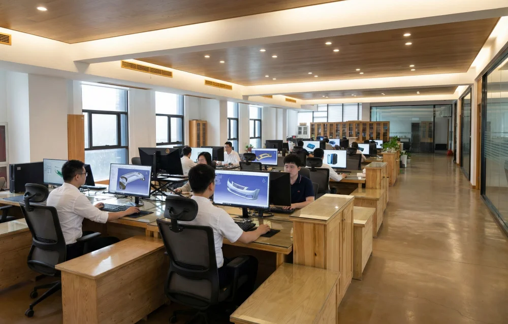
At SUASE, parting line design is treated as a critical engineering task rather than a simple machining detail. Every compression mold project is evaluated according to product geometry, material characteristics, production volume, and customer quality requirements.
Our engineering team focuses on:
- Product structure analysis.
- Optimized parting line layout.
- Material flow evaluation.
- Flash reduction strategies.
- Precision CNC machining.
- Mold trial verification.
- Continuous engineering improvement.
By combining practical molding experience with precision manufacturing technology, SUASE develops SMC molds that deliver stable production performance and long service life across automotive, electrical, sanitary ware, and industrial applications.
Frequently Asked Questions About SMC Mold Parting Line Design
1. What is the purpose of a parting line in an SMC mold?
The parting line separates the upper and lower mold halves, controls mold opening, supports venting, limits flash, and enables part removal after molding.
2. Why is parting line design important?
A properly designed parting line improves product appearance, reduces flash, enhances venting efficiency, simplifies demolding, and extends mold service life.
3. Can poor parting line design affect product quality?
Yes. Poor design may result in excessive flash, trapped air, dimensional variation, difficult demolding, and increased mold maintenance.
4. How can flash be reduced in compression molding?
Flash can be minimized through precise parting surface machining, proper mold alignment, sufficient mold rigidity, and optimized compression molding parameters.
5. Why are vent grooves often located along the parting line?
The parting line provides a natural path for trapped air and gases to escape during molding, helping reduce voids and improve part quality.
6. Does every SMC mold use the same parting line design?
No. The optimal parting line depends on product geometry, material flow characteristics, dimensional requirements, production volume, and mold structure.
7. How is the final parting line verified?
Engineers verify the design through mold trials, dimensional inspection, flash evaluation, venting performance analysis, and continuous production testing.
Conclusion
The SMC mold parting line is one of the most important factors influencing compression mold performance. A carefully engineered parting line contributes to stable material flow, effective venting, reduced flash, accurate dimensions, and efficient demolding.
As composite components become more complex in automotive, electrical, and industrial applications, parting line design plays an increasingly important role in ensuring manufacturing quality and long-term tooling reliability.
By integrating product analysis, mold engineering, precision machining, and systematic mold trials, professional mold manufacturers can significantly reduce development risks and improve production efficiency.
With extensive experience in SMC mold design and compression mold manufacturing, SUASE provides customized tooling solutions that help customers achieve consistent quality, shorter development cycles, and reliable long-term production.