
Flash is one of the most common defects encountered during SMC compression molding. A thin layer of excess material may appear along the parting line, around inserts, near holes, or at other locations where the molding compound escapes from the mold cavity.
Although flash is often treated as a simple trimming problem, excessive flash can indicate a deeper issue in the SMC mold, molding process, material charge or press condition. If flash becomes severe, it can increase trimming work, affect dimensional accuracy, damage the mold parting surface and reduce production efficiency.
Effective SMC mold flash control therefore requires more than increasing clamping pressure. The mold sealing condition, parting-line design, cavity pressure, material flow, venting and machine alignment must be considered together.
What Is Flash in SMC Compression Molding?
Flash is unwanted cured or partially cured SMC material that extends beyond the intended part boundary. It is normally formed when molding compound enters a small clearance between two mold surfaces or escapes through a local gap during compression.
Common flash locations include:
- Mold parting lines
- Insert interfaces
- Core and cavity transitions
- Movable mold components
- Ejector-related areas
- Deep ribs and local features
- Perimeter sealing areas
A small amount of flash can sometimes be removed during post-processing. However, continuous or excessive flash usually means that the material is finding a flow path outside the intended cavity boundary.
Why Does SMC Mold Flash Occur?
The basic mechanism is relatively simple:
Material pressure + available clearance + insufficient mold sealing → material leakage → flash.
During compression molding, the SMC charge is compressed and flows through the cavity. As the material fills the mold, pressure develops inside the cavity. If the parting surfaces cannot adequately resist material flow, SMC can be forced into the available gap.
The amount of flash is influenced by several variables:
- Parting-line condition
- Mold clearance
- Clamping force
- Material charge weight
- Charge placement
- SMC viscosity
- Mold temperature
- Closing speed
- Press parallelism
- Mold wear
- Insert fit and alignment
Parting Line Design Is Critical for Flash Control
The parting line is one of the most important areas in an SMC compression mold because it defines where the mold halves meet and where excess material is prevented from leaving the cavity.
A poorly designed parting line can create an unstable sealing condition. If the parting surface is too narrow, uneven, interrupted or located in an area exposed to excessive material flow, flash may occur repeatedly even when the press provides sufficient clamping force.
A well-designed parting line should consider:
- Material flow direction
- Expected cavity pressure
- Part geometry
- Trimming requirements
- Parting surface width
- Local reinforcement features
- Ease of mold maintenance
The objective is not simply to create a visible separation between the mold halves. The parting line should also act as a controlled material boundary.
How Mold Clearance Affects SMC Flash
Clearance between mating mold components is another major factor in flash formation. As the mold operates repeatedly, parting surfaces, inserts, slides or other moving components may gradually wear.
Even a relatively small increase in clearance can provide a flow path for SMC under compression.
The relationship can be understood as:
Wear → increased local clearance → easier material leakage → thicker flash.
This is why flash can become progressively worse after a mold has completed a large number of production cycles.
When investigating flash, the actual mold condition should therefore be checked rather than assuming that the original CAD geometry is still representative of the production mold.

Clamping Force and Flash
Clamping force must be sufficient to keep the mold closed against the pressure generated by the molding compound. If the effective closing force is insufficient, the mold can separate slightly at vulnerable locations.
This separation may be very small, but it can be enough for SMC to enter the parting-line gap.
However, simply increasing press pressure is not always the correct solution.
Excessive clamping force can increase:
- Mold stress
- Press loading
- Parting-surface wear
- Energy consumption
- Potential mold deformation
The correct approach is to determine whether the problem originates from insufficient clamping force or from an ineffective mold sealing condition.
Material Charge Weight and Flash
Incorrect charge weight is another common cause of excessive flash.
If too much SMC is placed into the mold, the excess material must go somewhere as the cavity closes. When the available cavity volume is insufficient, material can be pushed toward the parting line and other escape paths.
Therefore:
Excess charge → increased material displacement → higher cavity pressure → increased flash risk.
Charge weight should be controlled according to the actual part volume, material density, process conditions and required overflow or trimming strategy.
Charge Placement Also Influences Flash
Even when the total charge weight is correct, poor charge placement can create local flash.
SMC placed too close to a parting line may reach the perimeter before the cavity is fully consolidated. Similarly, an unbalanced charge can cause material to flow disproportionately toward one side of the mold.
Charge layout should therefore be considered together with:
- Cavity geometry
- Rib locations
- Material flow direction
- Insert positions
- Vent locations
- Parting-line geometry
SMC Viscosity and Mold Flash
SMC does not behave like a rigid solid during compression molding. Its flow behavior changes with temperature, pressure, material formulation and cure state.
If the material becomes highly fluid during a critical stage of mold closing, it can more easily enter small gaps in the parting surface.
Mold temperature therefore has an indirect effect on flash:
Mold temperature → SMC viscosity and cure rate → material flow behavior → cavity pressure distribution → flash tendency.
Excessive temperature variation between different areas of a large mold can make flash appear only in certain regions. This is one reason why temperature control should be evaluated when flash occurs in a localized and inconsistent pattern.
How Venting Can Affect Flash
Air and volatile gases must be removed from the mold cavity during compression molding. Proper venting helps the material fill the cavity while reducing trapped air.
However, venting and flash control must be balanced. If a vent is too large, poorly positioned or damaged, it can become an unintended material flow path.
A good venting design should allow gases to escape while limiting the amount of SMC entering the vent.
This requires consideration of:
- Vent depth
- Vent width
- Vent location
- Material viscosity
- Expected flow direction
- Ease of cleaning
Flash Around Inserts and Local Features
Flash is not always generated at the main mold parting line. Inserts, cores, movable components and other interfaces can also create local leakage paths.
Typical causes include:
- Insert misalignment
- Insufficient contact between mating surfaces
- Wear of insert edges
- Incorrect clearance
- Thermal expansion differences
- Damage caused during cleaning or maintenance
When flash repeatedly appears around one insert, replacing the entire mold is rarely the first solution. The insert fit, contact surface and local geometry should be inspected first.
Press Parallelism and Mold Flash
The mold depends on the compression press to apply force evenly across the tooling. If the upper and lower platens are not sufficiently parallel, the mold may experience uneven closing conditions.
One side of the mold may close correctly while another side retains a larger effective gap.
This can produce a typical defect pattern:
Uneven press alignment → uneven mold closure → local parting-line gap → localized flash.
If flash repeatedly occurs on one side or in a particular corner of a large component, press parallelism and mold installation should be included in the investigation.
Common SMC Mold Flash Problems and Solutions
| Flash Symptom | Possible Cause | Recommended Action |
|---|---|---|
| Continuous flash along the entire perimeter | Parting-line sealing problem or excessive charge | Inspect parting surfaces, charge weight and mold closure |
| Flash only on one side | Press or mold alignment problem | Check platen parallelism and mold installation |
| Flash becomes worse over time | Mold wear or damaged parting surface | Inspect and repair the sealing surfaces |
| Flash around inserts | Insert clearance or misalignment | Check insert fit and local contact condition |
| Flash near vents | Improper vent geometry | Inspect vent depth, width and location |
| Flash increases after process adjustment | Higher flowability or cavity pressure | Review temperature, closing speed and charge placement |
How to Reduce Flash During SMC Mold Trial
Flash should be investigated systematically during mold trials rather than corrected by changing multiple parameters simultaneously.
A practical trial sequence is:
- Confirm the correct SMC material and charge weight.
- Check charge placement and orientation.
- Confirm mold temperature distribution.
- Inspect mold parting surfaces.
- Check press parallelism and mold installation.
- Review closing speed and compression conditions.
- Inspect vents and local gaps.
- Measure flash thickness and location.
- Adjust one variable at a time.
- Record the results for repeatable production settings.
This approach helps distinguish a mold-design problem from a process-control problem.
Why Flash Should Not Simply Be Trimmed Away
Trimming is a normal post-molding operation for many SMC components, but relying on trimming to compensate for uncontrolled flash can create long-term production problems.
Excessive flash can lead to:
- Longer trimming cycles
- Higher labor requirements
- Increased material waste
- Inconsistent part dimensions
- Higher risk of damage during trimming
- Faster wear of trimming tools
- Potential damage to the mold parting surfaces
More importantly, uncontrolled flash may indicate that the mold and molding process are not operating within their intended design window.
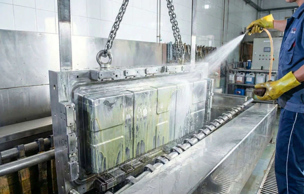
SMC Mold Maintenance for Flash Prevention
Preventive mold maintenance is one of the most effective ways to control flash over the life of the tooling.
Maintenance should include regular inspection of:
- Parting-line surfaces
- Cavity and core edges
- Guide pins and bushings
- Insert interfaces
- Venting areas
- Ejector components
- Heating system
- Fastening components
Contamination on the parting surface should also be removed because cured resin, fibers and other deposits can prevent complete mold closure.
A small deposit on a sealing surface can create a local gap. Under compression, that gap can become a channel through which SMC escapes.
Repairing an SMC Mold with Excessive Flash
When an existing mold develops excessive flash, repair should begin with diagnosis rather than immediate material removal or welding.
The repair process may include:
- Identify the exact flash location.
- Measure the flash pattern and thickness.
- Inspect the parting surface.
- Check for wear, dents and local deformation.
- Verify insert alignment and clearance.
- Check guide-system condition.
- Verify press parallelism.
- Determine whether welding or surface restoration is required.
- Re-machine the repaired area when necessary.
- Conduct a trial molding and dimensional inspection.
The repair objective should be to restore the intended geometry and sealing relationship, not simply to remove visible flash from the finished part.
SMC Mold Design Strategies for Better Flash Control
Flash control is most effective when it is considered during the initial mold design stage.
Important design considerations include:
- Stable and well-defined parting surfaces
- Appropriate parting-line location
- Controlled clearances
- Proper venting design
- Suitable draft angles
- Reliable guide and alignment systems
- Appropriate insert interfaces
- Uniform mold heating
- Easy access for cleaning and maintenance
- Controlled trimming geometry
The goal is to create a mold that remains dimensionally stable and capable of controlling material flow throughout its expected production life.
SMC Mold Flash Control: A Practical Engineering Approach
When excessive flash occurs, the fastest solution is not necessarily the most effective one. A useful diagnostic framework is to separate the problem into four categories.
| Category | Questions to Check |
|---|---|
| Material | Is the material correct? Is charge weight controlled? Is viscosity changing? |
| Mold | Are the parting surfaces, inserts and vents in good condition? |
| Machine | Is the press parallel? Is sufficient and uniform clamping force available? |
| Process | Are temperature, closing speed, pressure and charge placement stable? |
This four-category approach can prevent unnecessary mold modification when the actual problem is caused by material or machine conditions.
Conclusion
SMC mold flash control is a combined tooling and process-control issue. Flash is created when molding compound finds an unintended flow path, but the reason that flow path exists can vary from parting-line wear and excessive clearance to incorrect charge weight, uneven mold temperature or press misalignment.
Effective control starts with a well-designed parting line and stable mold structure. During production, consistent material charge, controlled molding conditions, uniform heating, proper venting and regular inspection help maintain the sealing condition of the tooling.
For high-volume SMC production, minimizing flash at the source is generally more efficient than depending on increasingly intensive trimming operations. A properly engineered compression mold should control material flow while maintaining dimensional accuracy, repeatability and service life.
Frequently Asked Questions About SMC Mold Flash
What causes flash in SMC compression molding?
Common causes include excessive mold clearance, worn parting surfaces, insufficient or uneven clamping, excessive material charge, poor charge placement, incorrect temperature conditions, insert gaps and press misalignment.
Can increasing clamping pressure eliminate SMC flash?
Increasing clamping pressure may reduce flash when insufficient closing force is the actual problem, but it cannot correct worn parting surfaces, excessive clearance, poor insert fit or incorrect charge conditions.
How does mold temperature affect SMC flash?
Mold temperature affects SMC viscosity and curing behavior. Excessive or uneven temperature can change material flow and cavity pressure distribution, increasing the risk of localized flash.
Why does flash become worse as an SMC mold gets older?
Repeated production cycles can wear parting surfaces, inserts and alignment components. As local clearances increase or sealing surfaces become damaged, SMC can more easily escape from the cavity.
Is flash always a mold design problem?
No. Flash can result from the mold, material, press or process conditions. A systematic diagnosis is required before modifying the tooling.