A GMT panel that needs force to line up with its mounting points is not necessarily a panel with the wrong mould dimensions. In GMT molding, the material's flow and cooling history also influence the final shape. Moving a tool feature may correct a stable offset, but it will not necessarily resolve variation caused by the forming process.
The practical first step is to separate three questions: does the mould match the intended geometry, does the material fill that geometry consistently, and does the cooled part retain the required mounting shape?
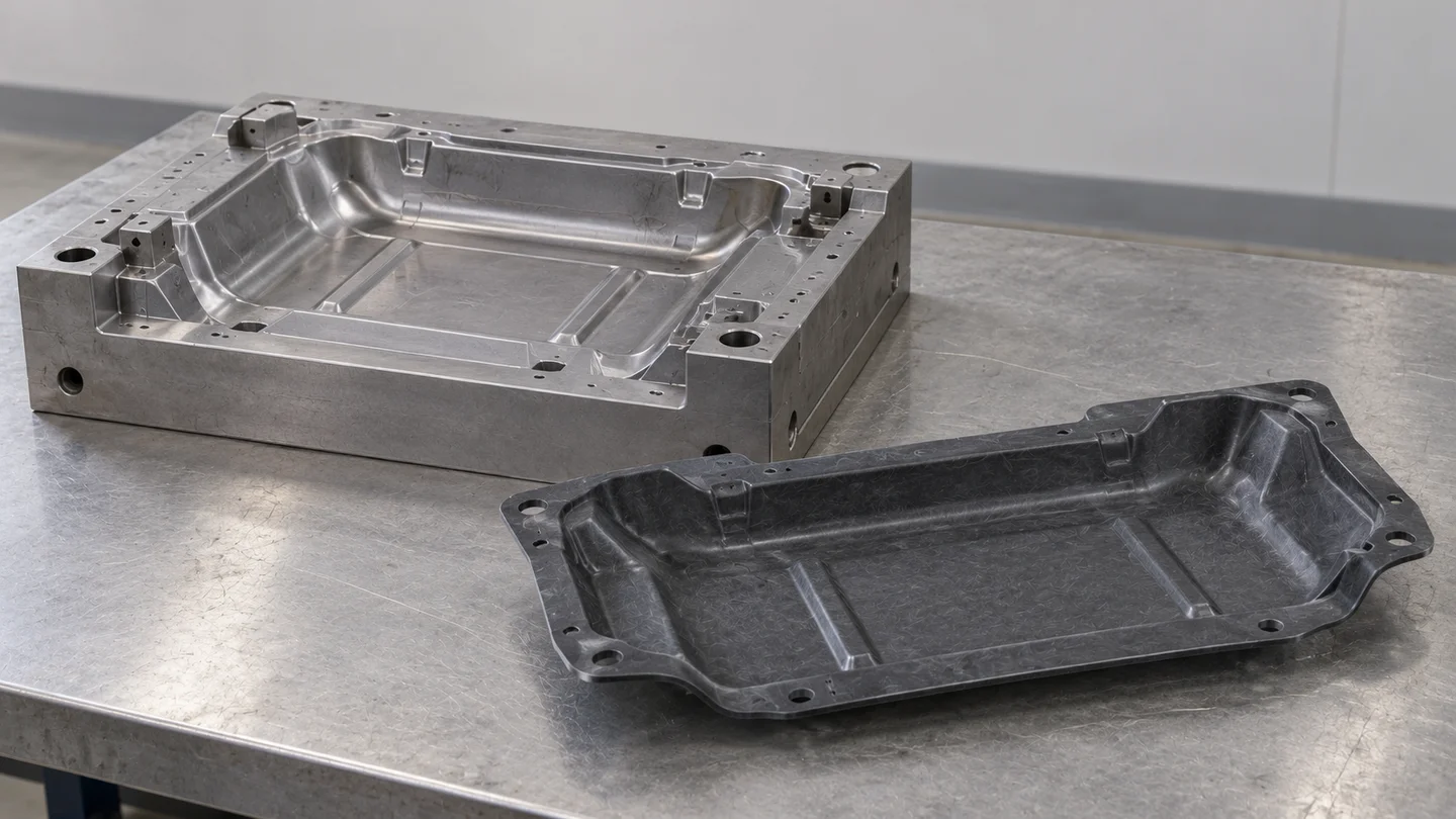
GMT is formed by heating and cooling, not thermoset curing
GMT means glass mat thermoplastic: glass-fibre reinforcement held in a thermoplastic matrix. The selected grade determines the polymer and reinforcement arrangement; GMT should not be assumed to mean carbon-fibre cloth or one universal material formulation.
In a typical compression-moulding route, prepared blanks are heated, transferred to the tool and pressed into shape. The part then cools sufficiently for removal. This differs from the chemical curing of a thermoset compound. Blank temperature, transfer time, charge placement and cooling therefore belong in the tooling discussion alongside the part drawing. GMT process research explains the connection between forming, cooling and dimensional change.
Check the mounting condition before compensating the tool
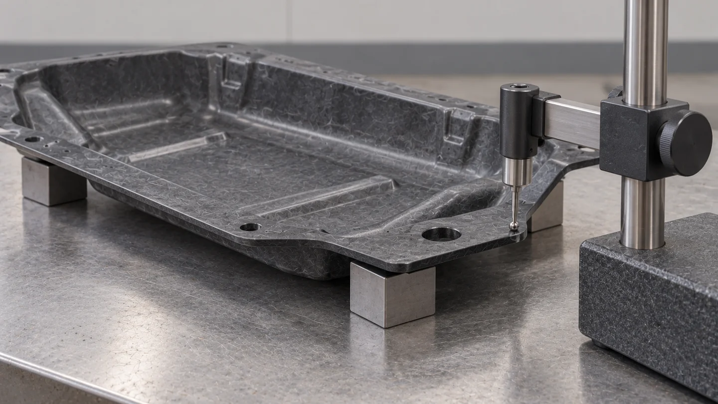
Suppose an underbody panel sits correctly at two mounts but lifts at a third. First inspect it in the support condition defined by the drawing or assembly requirement. Forcing the panel flat during measurement can hide the shape that the assembly actually receives.
A consistent offset across several parts points to a different investigation from an offset that changes between shots. Check the affected mould surface and the measurement datum, then compare material grade, blank arrangement and forming records. Possible process contributions should be investigated rather than treated as a confirmed cause from appearance alone.
For a stable geometry correction, SUASE's tooling review can focus on the corresponding forming surface and mounting land. Where the variation changes with the forming conditions, the review also needs to consider thermal management and material flow. This connects the proposed tool change to the observed problem before steel is removed.
A rib change also changes the material's route
Adding a rib or tightening a corner changes more than the drawing outline. It can change the distance and direction the heated charge must flow, and how the glass reinforcement moves into the feature. A deeper rib is not automatically a stronger rib if the resulting material distribution is unsuitable.
Review the rib, wall transition and nearby mounting area as one local design. Gentle transitions, an appropriate charge arrangement and a practical release direction need to work together. Any proposed radius, thickness or forming condition should follow the selected material and part requirements, rather than a generic value copied from another application.
SUASE's documented GMT tooling scope includes underbody systems and structural reinforcement. Its thermoplastic compression tooling provides a relevant starting point for discussing these coupled design and forming questions; suitability for a particular component still depends on its requirements.
Compare the result at the interface that matters
After a proposed change, compare parts using the same mounting datums, support condition and agreed temperature or conditioning state. Record which tool revision, material and forming setup produced each part. Check the location that was difficult to assemble, not just an easier overall dimension.
If the feature also carries a structural load, dimensional fit is only one part of acceptance. The relevant load and support assessment must cover the revised geometry and material arrangement.
For a GMT molding project with an assembly mismatch, share an existing drawing or mark the troublesome mounting location with SUASE. That is enough to begin a focused discussion about whether the next step belongs in the tool geometry, the forming conditions, or both.