Venting is an important part of compression mold design, especially when molding SMC, BMC, and other thermoset composite materials. During compression molding, air and gases inside the cavity need to escape as the material fills the mold. If the venting system is poorly designed, trapped air can contribute to surface defects, voids, incomplete filling, burn marks, and inconsistent part quality.
However, effective venting is not simply a matter of adding more vents. Vent location, vent geometry, parting line design, material flow, mold pressure, and flash control must be considered together.
For automotive and industrial composite components, a well-designed venting system should provide sufficient gas evacuation while minimizing unwanted material leakage and maintaining the dimensional accuracy of the molded component.
Why Is Venting Important in Compression Molding?
When the upper and lower mold halves close, the cavity contains a certain amount of air. As the SMC or other molding compound begins to flow under pressure, this air must be displaced.
At the same time, the molding material may release volatile components or gases during heating and curing. If these gases cannot escape efficiently, pressure can build up in localized areas of the cavity.
Poor venting may result in:
- Air entrapment.
- Voids and porosity.
- Surface pits or blisters.
- Burn marks.
- Incomplete filling.
- Weld or flow-related surface defects.
- Inconsistent surface quality.
- Local dimensional variation.
Therefore, venting should be considered during the initial mold design stage rather than treated as a modification after the first failed mold trial.
How Does Air Move During Compression Molding?
Understanding material flow is essential for determining where vents should be located.
As the mold closes, the molding compound spreads through the cavity. The material flow gradually pushes air toward the remaining open areas of the cavity.
The final regions reached by the material are often potential locations for trapped air.
These areas may include:
- Deep recessed sections.
- Corners and transitions.
- Rib intersections.
- Boss areas.
- High points or enclosed geometries.
- Regions opposite the initial material charge.
For this reason, vent locations should be determined according to the expected material flow path rather than distributed randomly around the mold.
The First Step: Analyze the Material Flow
Before designing the venting system, the mold designer should understand how the material is expected to fill the cavity.
Several factors influence material flow:
- Material charge size.
- Charge location.
- Part geometry.
- Wall thickness.
- Rib configuration.
- Molding temperature.
- Compression speed.
- Material viscosity.
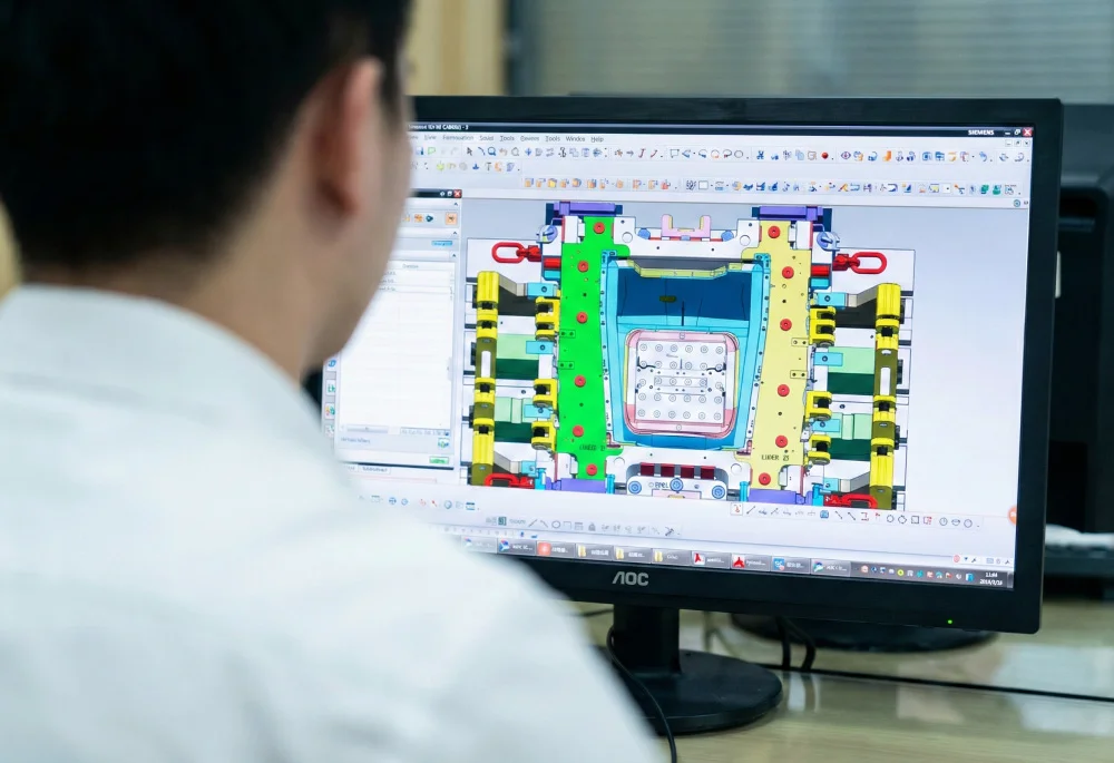
For complex automotive components, material flow simulation can be useful for identifying potential air-trap locations before the mold is manufactured.
For simpler parts, engineering experience combined with product geometry and previous trial data can also provide a practical basis for vent placement.
Where Should Vents Be Located?
There is no universal vent layout that works for every compression mold. The appropriate location depends on the product geometry and material flow pattern.
In general, vents should be considered in areas where air is likely to become trapped as the material reaches the end of its flow path.
Parting Line Areas
The parting line is one of the most practical locations for venting because the mold already has an interface between the upper and lower halves.
Controlled venting can be incorporated into suitable parting surfaces to allow air and gases to escape while limiting excessive material leakage.
Deep Cavities
Deep recessed areas can trap air, particularly when the cavity geometry creates a relatively enclosed region.
Additional venting may be required near the end of the material flow path in these areas.
Rib and Boss Areas
Ribs, bosses, and intersections can create small pockets where air becomes difficult to remove.
These areas should be reviewed carefully during mold design, especially when the component contains a large number of reinforcing features.
Parting Line Venting
For many compression molds, venting through the parting surface provides a simple and effective solution.
The venting geometry must be carefully controlled because the same gap that allows air to escape can also allow molding material to flow out of the cavity.
If the vent is too large, excessive flash may occur. If it is too restrictive, air evacuation may be insufficient.
The practical objective is therefore to create a controlled gas path while maintaining acceptable flash levels.
Vent Depth and Vent Width
Vent dimensions should not be selected using a single universal value. The appropriate geometry depends on the molding compound, viscosity, fiber content, mold temperature, pressure, surface requirements, and tooling configuration.
In general, the vent should provide sufficient flow resistance for gas evacuation while limiting the amount of molding compound entering the vent.
Important variables include:
- Vent depth.
- Vent width.
- Vent length.
- Number of vents.
- Distance between vents.
- Connection to the external atmosphere.
For production tooling, these dimensions should be validated through actual molding trials rather than treated as fixed theoretical values.
How to Balance Venting and Flash Control
One of the most important challenges in compression mold venting is finding the right balance between gas evacuation and flash control.
If the vent is too restrictive, the mold may suffer from trapped air.
If the vent is too open, molding compound may enter the vent and create excessive flash or require frequent cleaning.
A practical design therefore aims for:
- Efficient air evacuation.
- Controlled resin or compound leakage.
- Minimal visible vent marks.
- Easy mold cleaning.
- Stable performance over repeated cycles.
This balance is particularly important for automotive components where both dimensional accuracy and surface appearance are closely controlled.
Continuous Vents vs. Local Vents
Different products may require different venting strategies.
Continuous Venting
A continuous venting path can provide a relatively consistent gas evacuation route along an appropriate section of the parting line.
This approach may be useful for larger components or geometries where air can migrate toward a common perimeter region.
Local Venting
Local vents can be added around specific air-trap locations, such as deep cavities, ribs, bosses, or isolated geometric features.
A combination of continuous and local venting is often more practical than relying on one method for every part.
Venting for SMC Compression Molds
SMC molding presents several specific considerations because the material contains reinforcing fibers and resin, and its flow behavior changes with temperature and pressure.
The venting design should take into account:
- SMC formulation.
- Fiber content.
- Material viscosity during molding.
- Cure characteristics.
- Part thickness.
- Mold temperature.
- Compression pressure.
The vent design used for one SMC component should not automatically be copied to another component with significantly different geometry or material characteristics.
Venting and Mold Temperature
Mold temperature can influence both material flow and curing behavior. As the material temperature increases, its viscosity may change significantly, which can affect how quickly the cavity fills and how air moves through the mold.
Temperature distribution is therefore indirectly related to venting performance.
A mold with significant temperature variation may produce inconsistent material flow, meaning that the locations where air becomes trapped can also change.
For large compression molds, stable heating and good thermal balance can therefore support more predictable venting behavior.
Venting Around Ribs and Deep Features
Modern composite components often contain integrated ribs to increase stiffness without excessive material thickness.
However, ribs can also create difficult-to-fill regions.
Particular attention should be paid to:
- Rib intersections.
- Deep narrow channels.
- Closed pockets.
- Bosses.
- Sharp geometry transitions.
If air becomes trapped in these regions, the resulting defect may not always be visible from the outside. Internal voids or incomplete filling can affect the mechanical performance of the component.
Vacuum-Assisted Venting
For certain complex compression molding applications, conventional passive venting may not provide sufficient air removal.
Vacuum-assisted systems can be considered when:
- The component has complex geometry.
- Air traps are difficult to eliminate.
- High surface quality is required.
- The material system is sensitive to trapped gases.
- The part has deep or enclosed regions.
Vacuum should not be regarded as a replacement for good mold venting. It is better viewed as an additional process tool when the geometry or material system requires enhanced air removal.
Common Venting Design Mistakes
Adding Too Few Vents
A small number of vents may not provide sufficient gas evacuation for a large or complex cavity.
Placing Vents Without Considering Flow
Vent positions that do not correspond to actual air-trap locations may have limited effectiveness.
Making Vents Too Large
Oversized vents can increase flash and create additional finishing work.
Ignoring Deep Features
Deep pockets, ribs, and bosses can trap air even when the main cavity has adequate perimeter venting.
Treating Venting as an Afterthought
Trying to solve all air-trap problems after the mold has already been manufactured can result in unnecessary machining modifications and trial costs.
How to Validate Compression Mold Venting
The effectiveness of a venting system should be confirmed through mold trials.
During trial production, engineers should inspect:
- Surface defects.
- Burn marks.
- Voids.
- Incomplete filling.
- Flash distribution.
- Vent marks.
- Part dimensional stability.
If defects consistently appear in a particular area, the location should be compared with the expected material flow and air evacuation path.
The venting system can then be adjusted through controlled modifications rather than making multiple changes simultaneously.
How to Troubleshoot Poor Venting
When a molded part shows evidence of trapped air, engineers should first identify whether the problem is actually caused by insufficient venting.
Other possible causes include:
- Incorrect material charge placement.
- Improper molding temperature.
- Incorrect compression speed.
- Material contamination.
- Excessive moisture.
- Insufficient mold pressure.
- Unbalanced material flow.
A systematic troubleshooting process is more effective than simply increasing the number or size of vents.
Venting Design for Large Automotive Compression Molds
Large automotive components such as battery covers, underbody panels, wheel wells, seat structures, and body panels may contain complex surfaces and extensive reinforcing features.
For these molds, venting should be integrated with:
- Parting line design.
- Material charge layout.
- Flow analysis.
- Heating system design.
- Mold rigidity.
- Flash control.
- Demolding strategy.
This integrated approach helps prevent the venting system from conflicting with other critical mold functions.
The Relationship Between Venting and Mold Maintenance
Vents are exposed to molding compounds and may gradually become contaminated or blocked during production.
A venting system should therefore be designed with maintenance in mind.
Good maintenance design can provide:
- Easy access for cleaning.
- Reduced material accumulation.
- Clear inspection points.
- Simple replacement or repair where necessary.
Regular vent cleaning is particularly important when the mold is used for high-volume production.
A Practical Compression Mold Venting Checklist
Before finalizing a compression mold, the following questions should be reviewed:
- Have the expected material flow paths been evaluated?
- Have potential air-trap locations been identified?
- Are deep cavities and enclosed features properly vented?
- Is the parting line suitable for controlled venting?
- Are vent dimensions appropriate for the material system?
- Has flash control been considered?
- Is the venting system compatible with the heating and molding process?
- Can the vents be cleaned and maintained easily?
- Has the venting concept been validated through mold trials?
This checklist can help identify potential problems before the tooling enters regular production.
Why Venting Should Be Considered During Mold Design
A compression mold is a complete engineering system rather than simply a cavity and core. Material flow, heating, pressure, venting, shrinkage, parting lines, and demolding all interact during the molding cycle.
When venting is considered from the beginning, the tooling designer can integrate the gas evacuation path into the mold structure instead of relying on late-stage modifications.
This can reduce trial-and-error work and improve the consistency of production parts.
Conclusion
Compression mold venting design is essential for achieving consistent quality when molding SMC, BMC, and other composite materials. Effective venting removes trapped air and gases while controlling flash and maintaining the dimensional integrity of the mold.
The best venting strategy depends on the individual component. Mold designers should evaluate material flow, product geometry, deep features, parting surfaces, temperature conditions, and production requirements before determining vent locations and dimensions.
For complex automotive compression molds, venting should be developed together with material charge layout, heating, parting line design, and mold trial planning. This engineering approach provides a more reliable path toward stable production.
SUASE provides compression mold and composite tooling solutions for automotive and industrial applications, with engineering considerations covering mold structure, material flow, heating, venting, dimensional control, and trial validation.
Frequently Asked Questions About Compression Mold Venting
Why is venting necessary in a compression mold?
Venting allows air and gases inside the mold cavity to escape during material flow and curing. Without adequate venting, trapped air can cause voids, surface defects, burn marks, and incomplete filling.
Where should vents be placed in a compression mold?
Vents are generally placed near potential air-trap locations and the end of expected material flow paths. Parting lines, deep cavities, ribs, bosses, and enclosed regions may require special attention.
Can compression molds use parting line vents?
Yes. Parting line venting is commonly used because it provides a practical path for air evacuation. However, the vent geometry must be controlled to prevent excessive flash.
How large should a compression mold vent be?
There is no single universal vent dimension. Vent geometry depends on the material, fiber content, viscosity, mold temperature, pressure, product geometry, and surface requirements. Actual molding trials should be used to validate the design.
What happens if a compression mold has too much venting?
Excessive venting can allow more molding compound to escape from the cavity, increasing flash and creating additional cleaning or finishing work.
Can vacuum replace normal mold venting?
Vacuum-assisted systems can improve air removal in certain complex applications, but they should normally complement rather than replace a properly designed passive venting system.