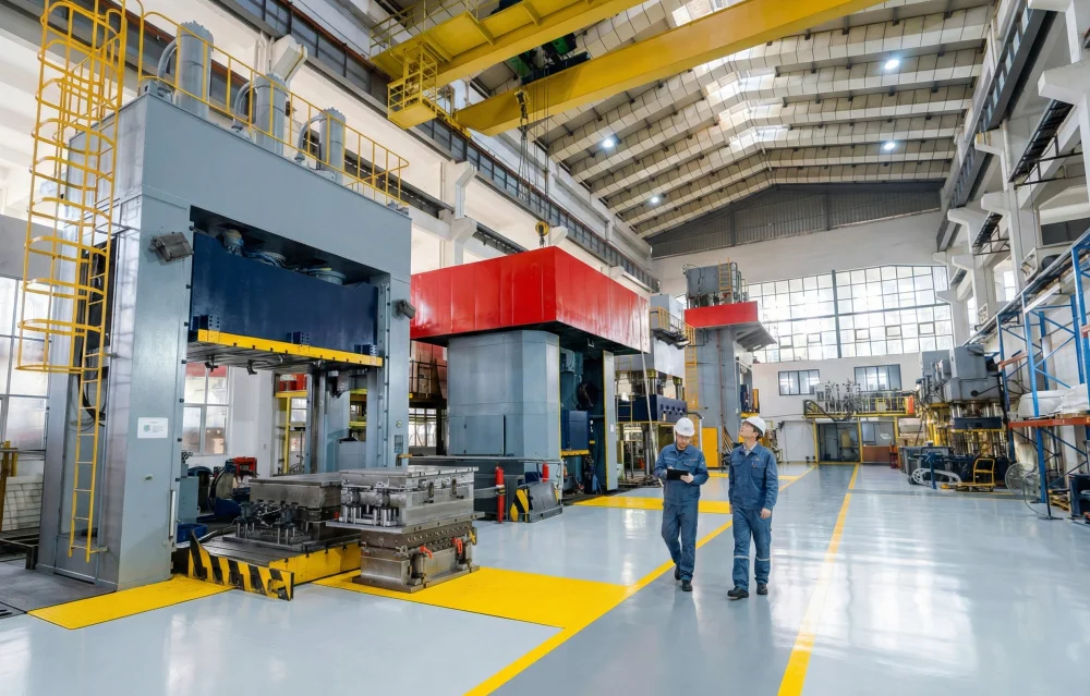
Mold acceptance is one of the most important stages before a newly manufactured compression mold is released for production. A mold may meet the basic drawing requirements and still require further verification of parting surfaces, dimensional accuracy, heating performance, venting, demolding, and molded-part quality.
For SMC mold acceptance, BMC mold acceptance, and other composite tooling projects, acceptance should therefore evaluate both the physical mold and the parts produced from it. For automotive applications, the inspection scope is often even more demanding because dimensional interfaces, surface appearance, functional features, and repeatability must all be controlled.
This guide presents a practical framework for compression mold acceptance, covering the major inspection items that should be considered before a mold enters regular production.
What Is Compression Mold Acceptance?
Compression mold acceptance is the formal process of verifying whether a newly manufactured mold meets the agreed technical, dimensional, functional, and production requirements.
The acceptance process normally includes several stages:
- Mold appearance inspection
- Dimensional inspection
- Parting-line and fitting inspection
- Surface inspection
- Heating and cooling system verification
- Venting inspection
- Demolding mechanism verification
- Trial molding
- Finished-part inspection
- Final documentation review
The exact acceptance criteria should be established between the customer and mold manufacturer before tooling production begins.
Why Is Mold Acceptance Important?
A compression mold directly affects the dimensional accuracy, surface quality, cycle stability, and repeatability of molded composite parts.
If a tooling problem is discovered only after mass production starts, correcting it can result in:
- Production delays
- Tool modification costs
- Part rejection
- Longer development time
- Unstable cycle times
- Inconsistent surface quality
A structured acceptance process provides an opportunity to identify these issues before the mold becomes part of the regular production system.
1. Mold Appearance Inspection
The first stage is a visual inspection of the complete mold.
The inspection should confirm that:
- There is no visible damage
- Machined surfaces are properly finished
- There are no obvious cracks or deformation
- Sharp burrs have been removed where appropriate
- Bolts and fasteners are properly installed
- Moving components operate correctly
- Labels and identification marks are complete
- Hydraulic, electrical, and heating connections are clearly identified
The mold should also be checked for contamination, excessive machining residue, oil leakage, and other conditions that could affect trial molding.
2. Mold Dimensions and Overall Geometry
The overall mold dimensions should be checked against the approved tooling design.
Important dimensions may include:
- Mold length and width
- Overall mold height
- Upper and lower mold dimensions
- Mounting-hole locations
- Locating features
- Press interface dimensions
- Opening and closing dimensions
These dimensions are particularly important when the mold will be installed on an existing compression molding press.
3. Product Cavity and Molded-Part Dimensions
The cavity geometry should be inspected against the approved product data.
Critical product dimensions should be identified before machining the mold.
Typical inspection items include:
- Overall part dimensions
- Critical profiles
- Hole locations
- Rib positions
- Flange dimensions
- Mounting interfaces
- Wall thickness features
- Datum locations
For complex automotive components, dimensional inspection may be performed using CMM measurement, scanning, or other suitable inspection methods.
4. Mold Parting Line Inspection
The parting line is a critical area of a compression mold because poor fitting can lead to excessive flash or dimensional problems.
The inspection should verify:
- Parting-line alignment
- Contact condition
- Parting-surface flatness
- Flash control
- Local fitting around complex geometry
A well-designed parting surface should provide reliable closure without creating unnecessary stress or excessive wear.
For SMC mold acceptance, parting-line inspection is particularly important because SMC material can generate flash along areas where the mold does not close consistently.
5. Cavity Surface Quality
Surface quality should be evaluated according to the requirements of the finished component.
Inspection may include:
- Surface roughness
- Polishing quality
- Texture consistency
- Visible machining marks
- Scratches
- Surface dents
- Coating condition
For visible automotive interior or exterior composite parts, the cavity surface can have a direct influence on the final appearance.
The required surface finish should therefore be defined clearly rather than relying only on general statements such as "polished."
6. Mold Fitting and Contact Inspection
The upper and lower mold halves should be checked for correct alignment and contact.
Depending on the tooling design, inspection can verify:
- Guide-pin alignment
- Locating-system accuracy
- Parting-surface contact
- Sliding components
- Replaceable inserts
- Core and cavity alignment
Poor alignment can cause uneven flash, dimensional deviation, premature wear, and damage to moving components.
7. Guide System Inspection
Guide pins, bushings, and other alignment components should operate smoothly throughout the mold opening and closing movement.
The inspection should check:
- Guide-pin alignment
- Guide-bushing condition
- Clearance
- Lubrication
- Smooth opening and closing
- Absence of abnormal interference
The guide system should maintain alignment under the expected operating conditions rather than only during manual inspection.
8. Heating System Acceptance
Temperature control is a critical part of compression molding because material curing and consolidation are strongly influenced by mold temperature.
For a heated mold, acceptance should verify:
- Heating circuit operation
- Temperature sensor installation
- Temperature controller operation
- Heating response
- Temperature uniformity
- Insulation condition
The actual temperature distribution should be measured rather than assuming that all mold zones reach the same temperature simply because the controller displays the same set point.
9. Temperature Uniformity
Uneven mold temperature can contribute to inconsistent curing, dimensional variation, surface defects, and differences in mechanical performance.
During acceptance, temperature measurements can be taken at multiple representative locations on the mold.
The measurement points should include areas that are structurally or thermally different, such as:
- Central cavity areas
- Corner areas
- Thick-section regions
- Thin-section regions
- Areas near inserts
- Areas near mold edges
The acceptance tolerance should be based on the material specification and process requirements rather than using an arbitrary value for every project.
10. Cooling System Inspection
If the mold incorporates cooling channels, their operation should be verified before production.
Inspection may include:
- Cooling-channel continuity
- Inlet and outlet identification
- Leak testing
- Flow condition
- Connection quality
- Temperature response
Effective cooling can improve cycle stability and help control part dimensions after molding.
11. Venting System Inspection
Venting is important because trapped air and volatile gases can affect molded-part quality.
A mold acceptance inspection should verify that designed vents are present and correctly positioned.
Potential vent locations include:
- Deep cavities
- Rib intersections
- High points in the cavity
- Material flow termination areas
- Potential air-trap locations
During trial molding, the actual part should also be inspected for evidence of insufficient venting.
12. Ejection and Demolding Inspection
The molded component should be released from the mold without excessive force or damage.
For molds using ejector systems, inspection should verify:
- Ejector movement
- Ejector alignment
- Ejector timing
- Return position
- Surface condition of ejector points
If vacuum-assisted demolding or other release mechanisms are used, their operation should also be verified during the trial.
13. Mold Safety Inspection
Safety-related features should be checked before the mold is connected to production equipment.
Depending on the mold design, this may include:
- Mechanical stops
- Limit switches
- Hydraulic connections
- Electrical connections
- Thermal protection
- Moving-part clearance
- Locking mechanisms
The mold should be compatible with the safety requirements of the production press.
BMC Mold Acceptance
BMC mold acceptance follows many of the same principles as SMC tooling acceptance, but the material behavior and component geometry can create different process considerations.
Particular attention may be given to:
- Material filling behavior
- Complex ribs and bosses
- Vent locations
- Surface quality
- Dimensional accuracy
- Flash control
- Insert positioning
Because BMC can be used for relatively complex molded geometries, cavity filling and venting should be evaluated carefully during the trial.
SMC Mold Acceptance
SMC mold acceptance should pay particular attention to large-area surfaces, material flow, flash control, dimensional stability, and temperature distribution.
Important checks include:
- Cavity dimensions
- Parting-line condition
- Surface finish
- Temperature uniformity
- Material flow
- Vent effectiveness
- Demolding performance
- Final part dimensions
For large SMC components, local temperature differences and uneven material distribution can have a noticeable influence on the finished part.
Composite Mold Acceptance
The term composite mold acceptance covers a broad range of tooling used for FRP, SMC, BMC, thermoplastic composites, sandwich structures, and other reinforced polymer components.
The acceptance criteria should therefore be adapted to the specific material and process.
For example, a mold used for a large sandwich panel may require different checks from a mold used for a compact BMC electrical component.
The following factors should be considered:
- Material processing temperature
- Pressure requirements
- Material flow
- Surface requirements
- Demolding method
- Dimensional stability
- Production cycle
Automotive Compression Mold Acceptance
Automotive compression mold acceptance can involve a wider range of requirements because automotive parts often combine structural, dimensional, appearance, and assembly functions.
Depending on the component, acceptance may include:
- Critical dimensional inspection
- Surface appearance inspection
- Mounting-point accuracy
- Hole-position verification
- Gap and flush requirements
- Flash control
- Part weight
- Functional testing
- Repeatability testing
For Class-A or highly visible surfaces, appearance inspection should be included in the tooling acceptance criteria.
14. Trial Molding Is Essential
A mold should not normally be accepted solely from dimensional inspection of the steel.
Trial molding provides evidence that the mold can actually produce the required component.
During a trial, engineers can evaluate:
- Material filling
- Flash
- Surface quality
- Fiber distribution
- Cure or consolidation
- Demolding
- Part dimensions
- Part weight
- Cycle time
The trial should use production-representative material and process parameters whenever possible.
15. Trial Part Dimensional Inspection
After trial molding, the finished component should be measured against the approved drawing or CAD data.
The inspection may include:
- Overall dimensions
- Critical profiles
- Hole positions
- Mounting interfaces
- Flatness
- Thickness
- Warpage
- Geometric tolerances
For complex components, 3D scanning or CMM measurement can provide a more complete comparison with the nominal geometry.
16. Surface Quality of Trial Parts
The molded part should be inspected for defects such as:
- Flow marks
- Surface waviness
- Blisters
- Voids
- Excessive flash
- Fiber print-through
- Scratches
- Local gloss variation
The specific acceptance criteria depend on whether the surface is visible, painted, coated, textured, or hidden after assembly.
17. Part Weight Verification
Part weight can be a useful process-control indicator for composite molded components.
Unexpected weight variation may indicate changes in:
- Material charge
- Material distribution
- Flash
- Part thickness
- Material loss
- Process conditions
The target weight and acceptable variation should be defined according to the product specification.
18. Flash Inspection
Flash is one of the most common issues checked during compression molding trials.
The inspection should evaluate:
- Flash thickness
- Flash location
- Flash consistency
- Ease of trimming
- Potential interference with assembly
Excessive flash may indicate problems with parting-line fitting, charge size, mold closing conditions, or process parameters.
19. Cycle Time Verification
A mold that produces acceptable parts but cannot achieve the required production cycle may still require optimization.
The trial should therefore record relevant process times, including:
- Loading time
- Mold closing time
- Compression time
- Curing or consolidation time
- Cooling time
- Demolding time
- Trimming time where applicable
The actual cycle should be compared with the agreed production target.
20. Repeatability Verification
One good trial part does not necessarily prove that a mold is ready for stable production.
Where appropriate, several consecutive parts should be produced using consistent process conditions.
The parts can then be compared for:
- Dimensions
- Weight
- Surface quality
- Flash
- Warping
- Assembly fit
Repeatability is particularly important for automotive and high-volume applications.
Acceptance Documentation
The final mold acceptance package should include the documents agreed for the project.
Typical documentation may include:
- Final mold drawings
- Dimensional inspection report
- Material certificates where applicable
- Temperature test records
- Leak test records
- Trial molding report
- Trial-part inspection report
- Maintenance instructions
- Spare-parts list
- Operating instructions
Clear documentation helps establish the technical baseline for future maintenance and production troubleshooting.
Compression Mold Acceptance Checklist
| Inspection Category | Main Acceptance Items |
|---|---|
| Mold Appearance | Surface condition, damage, burrs, identification and assembly |
| Dimensions | Overall mold size, mounting and locating dimensions |
| Cavity | Product geometry, profiles, holes and critical dimensions |
| Parting Line | Alignment, contact and flash control |
| Surface | Polishing, texture, roughness and appearance |
| Guide System | Alignment, clearance and smooth operation |
| Heating | Heating response, sensors and temperature uniformity |
| Cooling | Flow, leakage and temperature response |
| Venting | Vent location, condition and effectiveness |
| Demolding | Ejector or release mechanism operation |
| Trial Molding | Filling, curing, flash and surface quality |
| Trial Part | Dimensions, weight, warpage and assembly fit |
| Repeatability | Consistency across consecutive molded parts |
| Documentation | Inspection reports, drawings and maintenance information |
Common Problems Found During Mold Acceptance
Excessive Flash
Excessive flash may be related to parting-line fitting, mold alignment, material charge, or process conditions. The root cause should be identified instead of simply increasing trimming work.
Uneven Surface Quality
Surface differences may result from cavity finishing, temperature variation, material distribution, or processing conditions.
Dimensional Deviation
Dimensional problems can originate from tooling geometry, shrinkage assumptions, temperature distribution, material behavior, or process conditions.
Incomplete Filling
Incomplete filling can indicate unsuitable charge placement, insufficient material flow, inadequate pressure, or poor process design.
Demolding Difficulty
Difficult demolding may be caused by insufficient draft, excessive friction, unsuitable surface treatment, local undercuts, or an unsuitable release strategy.
Temperature Non-Uniformity
Uneven mold temperature can lead to inconsistent curing and dimensional variation. Heating layout, sensor positioning, insulation, and control parameters should be reviewed.
How to Define Mold Acceptance Criteria Before Tooling Production
Acceptance should not be treated as something decided only after the mold is finished.
The customer and tooling manufacturer should agree on the main criteria before mold manufacturing begins.
The agreement can define:
- Critical product dimensions
- General dimensional tolerances
- Surface requirements
- Temperature requirements
- Flash limits
- Part weight
- Cycle time
- Trial quantity
- Testing methods
- Required documentation
This makes the acceptance process more objective and reduces disagreements between the customer and supplier.
SMC, BMC and Automotive Mold Acceptance: What Changes?
| Application | Important Acceptance Focus |
|---|---|
| SMC Mold | Large surfaces, temperature uniformity, material flow, flash and dimensional stability |
| BMC Mold | Complex geometry, filling, venting, inserts, surface quality and dimensional accuracy |
| General Composite Mold | Material compatibility, processing temperature, surface, demolding and structural stability |
| Automotive Compression Mold | Critical dimensions, appearance, assembly interfaces, repeatability and production cycle |
Final Acceptance vs. Trial Acceptance
It can be useful to distinguish between initial trial acceptance and final production acceptance.
Trial acceptance confirms that the mold can produce parts close to the required specifications and identifies necessary modifications.
Final acceptance confirms that agreed dimensional, functional, appearance, cycle-time, and repeatability requirements have been achieved.
This approach can be particularly useful for complex automotive composite tooling where several rounds of optimization may be required.
Conclusion
A professional compression mold acceptance process should evaluate more than the physical appearance of the tooling. Dimensional accuracy, parting-line fitting, cavity surface quality, heating and cooling, venting, demolding, trial molding, finished-part inspection, and production repeatability all contribute to final mold performance.
For SMC mold acceptance and BMC mold acceptance, the inspection criteria should reflect the specific material behavior and component geometry. For automotive applications, additional attention should be given to critical dimensions, appearance, mounting interfaces, assembly fit, and production repeatability.
The most reliable approach is to define acceptance criteria before tooling production begins and then verify the mold through both dimensional inspection and representative trial molding. This creates a clear technical standard between the customer and mold manufacturer and provides a stronger foundation for stable series production.
Frequently Asked Questions About Compression Mold Acceptance
What should be checked when accepting a compression mold?
The main checks include mold dimensions, cavity geometry, parting-line fitting, surface quality, guide systems, heating, cooling, venting, demolding, trial molding, finished-part dimensions, weight, appearance, and repeatability.
What is the difference between SMC mold acceptance and BMC mold acceptance?
The general inspection framework is similar, but the focus can differ according to material behavior and part geometry. SMC tooling often requires particular attention to large surfaces, temperature uniformity, material distribution, and flash, while BMC tooling may require greater attention to complex cavities, ribs, bosses, inserts, and venting.
Is trial molding required for mold acceptance?
Trial molding is strongly recommended because dimensional inspection of the steel alone cannot confirm material flow, curing, surface quality, flash, demolding, or finished-part performance.
How is mold temperature checked during acceptance?
Temperature should be measured at multiple representative locations after the mold reaches the required operating condition. The measured distribution should be compared with the agreed process requirements.
Why is parting-line inspection important?
Poor parting-line contact can result in excessive flash, dimensional variation, premature wear, and unstable molding conditions.
What documents should be provided after mold acceptance?
Depending on the project, the final package may include dimensional inspection reports, final tooling drawings, temperature records, leak-test records, trial reports, part inspection reports, maintenance instructions, and spare-parts information.