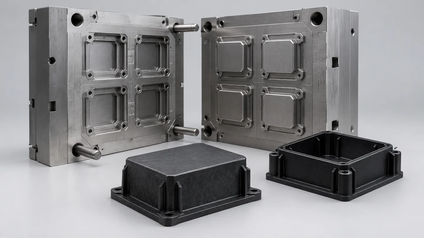
When a critical dimension on a BMC (bulk molding compound) industrial component varies between mold cavities—the spaces that form the parts—a tighter tolerance can lead to rejected parts. Editing the nominal cavity dimension may leave the difference between cavities unresolved.
For BMC molding by compression, reassess forming geometry together with material behavior, thermal management, pressure distribution, material flow and curing conditions. Surface, dimensional and structural requirements raise different tooling questions. The useful correction is one connected to the observed problem, rather than chosen from the drawing change alone.
SUASE supports precision BMC molding for electrical insulation, industrial components and high-precision thermoset parts. Its BMC scope includes multi-cavity systems, cavity balance and dimensional stability. For a revised component, a tooling proposal could connect the affected forming geometry with the conditions needed to meet the new requirement.
For a tighter surface requirement, assess how the face is formed
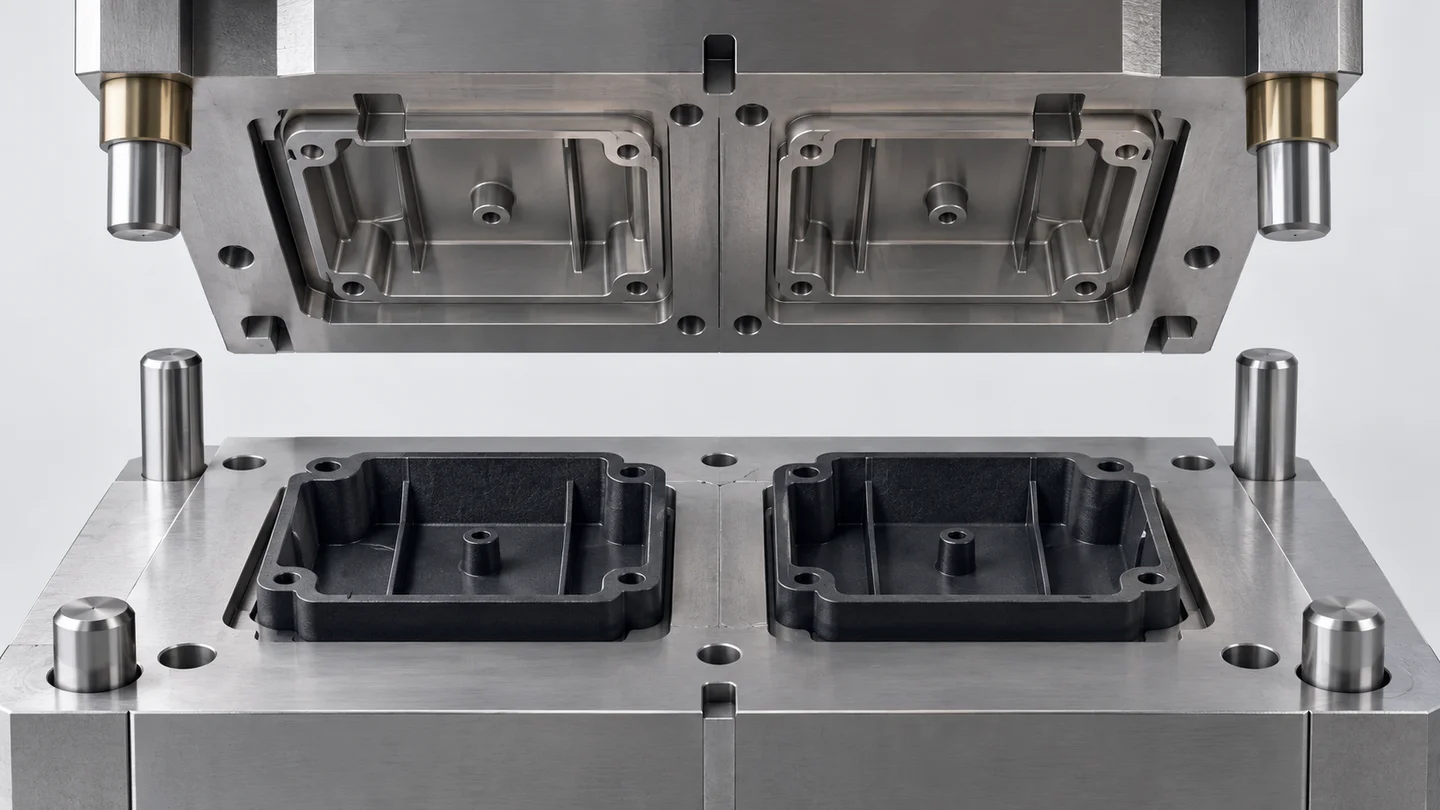
The forming face gives the part its intended surface geometry, while heat, pressure, time and material flow govern how the composite takes shape and cures. Curing is the hardening of the thermoset material during molding.
A revised surface requirement therefore raises two connected questions: does the forming face need a geometry change, and do thermal management or pressure distribution need reconsideration alongside flow and cure? A geometry correction addresses shape; it does not establish that the forming conditions suit the new surface requirement.
Compare the affected face against one agreed surface acceptance reference. For a multi-cavity tool, retain the cavity identity of each sample. Whether an issue repeats at the same location or differs between cavities helps direct the assessment, although the pattern alone does not establish its cause.
For a tighter tolerance, compare cavities before applying one correction
A dimensional tolerance defines the acceptable range around a drawing requirement. Tightening that range changes acceptance, but does not identify why the existing variation occurs.
If a feature shows a consistent departure from its target, reassessing its local forming geometry may be appropriate. If the result differs between cavities, applying the same geometry correction everywhere may leave that relative difference unresolved. Material behavior and forming conditions remain relevant in either situation.
SUASE’s BMC focus on multi-cavity systems and cavity balance is directly relevant here. Cavity balance concerns how consistently the cavities behave during forming. A proposed SUASE tooling assessment could examine the affected feature cavity by cavity, together with thermal management, pressure distribution and material flow, to determine whether local geometry, cavity balance or both warrant attention.
For the dimensional comparison, measure the same drawing-defined feature in its specified units under the same agreed measurement conditions. Keep departure from the target separate from the spread between cavities. The useful evidence is whether formed parts meet the revised tolerance across the affected cavities, rather than whether the tool drawing has been updated.
For a structural change, connect section geometry with material flow
Compression molding involves material movement and fiber orientation—the directions in which fibers lie in the formed part. These belong in a structural tooling decision alongside geometry and deformation, or how the part changes shape under load.
If a higher structural requirement leads to a proposed section change, assess that geometry together with material behavior, flow, pressure distribution and curing conditions. The revised section changes the shape the material must fill; its external dimensions alone do not establish the resulting structural behavior.
The relevant observation is deformation under the load and support conditions defined for the application, assessed against the structural requirement. Surface acceptance and dimensional conformity answer different questions and cannot substitute for that assessment.
This keeps the tooling decision connected to the actual requirement: a geometry change may be necessary, while material movement and forming conditions still need consideration with it.
Start with the feature that needs to change
If a revised BMC requirement is prompting repeated tool corrections, an existing drawing with the affected feature marked is a useful starting point for a conversation with SUASE. The first question to investigate together is whether the next correction should address local forming geometry, cavity balance or the conditions under which the material flows and cures.