
An existing BMC mold may be retained after a material or drawing revision, but the decision needs two questions answered: what has changed in the component requirement, and how does the selected compound behave in the intended molding process? Changing a cavity dimension is useful when it addresses an identified geometric requirement. It does not, by itself, control variation between molded parts.
Consider an illustrative housing with two locating faces. The nominal distance stays the same, while the permitted tolerance becomes tighter and a new BMC grade is proposed. Before deciding on a cavity correction, separate a consistent dimensional offset from part-to-part variation. Those observations point to different questions about the material, tool and molding conditions.
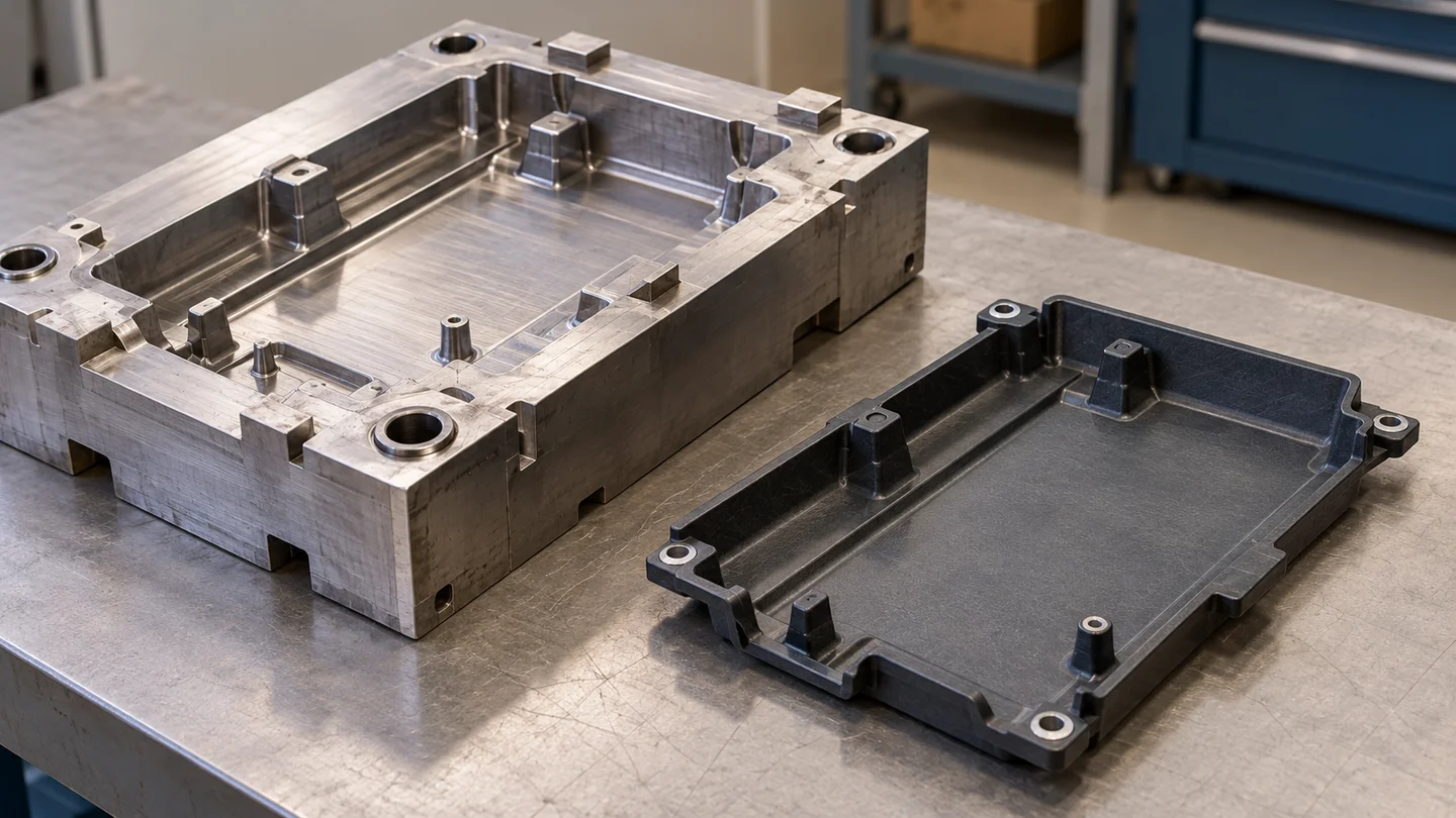
Start with the actual compound and forming route
Bulk molding compound (BMC) is a thermoset material, typically combining resin, short chopped glass reinforcement, fillers and additives. It is supplied uncured and cures during molding. IDI’s BMC material overview explains the formulation and short-fiber reinforcement; the material name alone does not identify a particular grade.
Suitable BMC grades are used in compression, injection and transfer molding. A revision to a compression mold should therefore be assessed against the selected compression-molding grade, rather than assuming that every BMC formulation has the same processing behavior or finished-part properties.
This becomes particularly useful when the material and drawing change together. Identify which requirement prompted the new grade—such as a dimensional, electrical or surface requirement—and which geometry is affected. The discussion then has a defined component target, rather than an open-ended request to “improve the mold.”
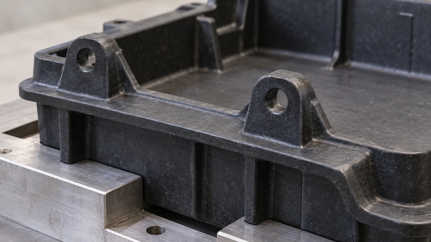
Read the dimensional pattern before choosing a cavity edit
For the locating-face example, use the same features, datum definition and agreed measurement conditions when comparing samples. Then distinguish the patterns below.
| Observation or drawing change | Question for the tooling review | Useful comparison |
|---|---|---|
| The nominal distance changes | Which forming surfaces define the revised distance? | Corresponding cavity geometry and molded dimensions against the new drawing. |
| Measurements show a consistent offset | Is the target geometry appropriate for the selected material and molding condition? | The direction of the offset across samples, together with tool geometry and process records. |
| Part-to-part variation remains wide | Which material, process or measurement conditions differ between samples? | Repeated measurements obtained under a defined, comparable setup. |
| Results differ between cavities | Is the difference associated with a particular cavity or its forming conditions? | Cavity-identified results, rather than one average for the whole tool. |
A dimensional offset and a wide spread are different problems. A geometry correction changes the dimensional target; it does not explain why otherwise comparable parts vary. Equally, a change in measurement support or datum can make two sets of results difficult to compare. Establishing that distinction helps avoid a tool modification that addresses the wrong question.
Connect the evidence to a practical SUASE review
SUASE’s documented BMC tooling services include mold design, maintenance and technical consultation. Its inspection capability includes comparing measured geometry with CAD data. These services provide a relevant starting point for discussing a revision to an existing BMC mold.
For the housing example, a proposed review could bring the affected drawing features, selected grade, cavity geometry and available sample measurements together. The outcome to discuss is specific: whether the existing forming surfaces can be retained, whether a trial should clarify the material–process pairing, or whether an identified feature warrants a tool modification. The project’s evidence determines the route.
Keep surface, electrical, heat and structural requirements separate from the dimensional conclusion. A sample that meets the locating distance answers that drawing question; any other requirement needs its own relevant acceptance basis.
If you are considering a BMC mold revision, share the affected feature on an existing drawing and explain what has changed. SUASE can use that starting point to discuss the tooling question and the sample evidence needed to choose the next step.