BMC Mold Design for Metal Inserts: Getting the Thread in the Right Place
A screw can enter a molded-in insert perfectly and still fail to line up with the mating assembly. The thread is usable; its position, angle or height relative to the finished part is wrong. For a customer buying BMC tooling, that difference matters more than how neatly the insert appears to sit in the open mold.
Good BMC mold design connects the insert's function to its location in the tool, the way it is loaded and the way the molded component will be inspected. SUASE's BMC tooling scope provides a starting point for that discussion. Here, the focus is BMC compression molding with inserts placed before molding—not an injection-molding runner layout or a heat-set installation into a finished thermoplastic part.
Start with the assembly that the insert must fit
Consider a BMC housing with two threaded inserts that secure a bracket. Both threads pass a thread gauge, but the bracket cannot sit flat without forcing one screw sideways. Checking thread size alone will not explain the problem.
The useful questions concern the finished assembly: which housing surface supports the bracket, where each thread axis must lie relative to that surface, and how far the metal face may stand above or below it. The distance between inserts matters, but so do their orientation and their relationship to the seating surface.
For a project review with SUASE, put those functional references on the part drawing before discussing a tighter tooling tolerance. Otherwise, the mold may locate an insert accurately against a feature that the customer's assembly never uses. An agreed reference scheme gives the toolmaker and the receiving inspector the same question to answer.
Locate the insert without making loading fragile
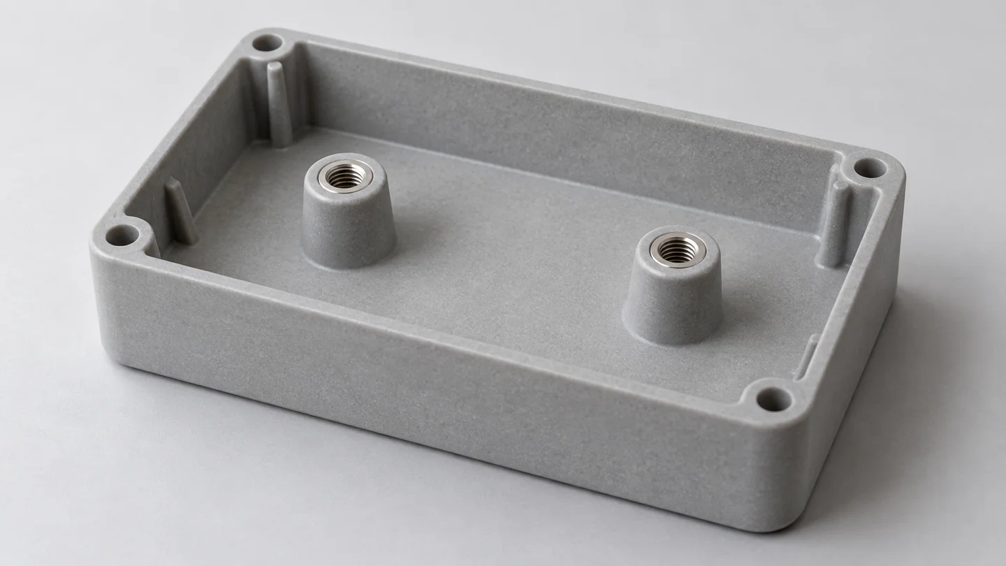
A locating pin can establish an insert's axis, while an appropriate seating feature establishes its height. The actual arrangement depends on the insert geometry and the tool's opening and release directions; it should not be selected from a generic insert illustration.
Two different jobs must be considered: holding the insert during molding and retaining it in the finished component. A good fit on a locating pin does not establish the final component's resistance to insert rotation or pull-out. Insert supplier SPIROL distinguishes core-pin positioning from the external retention features that the surrounding material must fill. The pin fit and the final retention performance therefore need separate checks. (SPIROL molded-in inserts →)
The practical SUASE tooling discussion is therefore specific: which surfaces locate this insert, which openings must remain free of compound, and how will the insert and molded part release without fighting the locating arrangement? If the insert has a preferred orientation, the loading concept should make a reversed part detectable before closure. That is more useful than relying on an operator to spot a subtle difference after the tool is already charged.
Check the loading sequence in the space the operator actually has
An insert that can be placed into a bare cavity may become difficult to reach when the BMC charge, adjacent inserts and loading equipment are considered together. A gripper also needs room to withdraw after seating the insert. The sequence should be reviewed with the proposed tool opening and access arrangement, not only in a view of the finished part.
For the two-insert housing, follow each step on the tooling concept: locate the inserts, confirm seating, place the charge by the agreed method, and clear the loading equipment before closure. This is a design review sequence, not permission to work inside an unguarded press. The production loading method must follow the press's safety system.
SUASE and the customer's molding team can use this review to identify where access or visibility needs to change before machining. The intended benefit is a loading arrangement that can be checked consistently, rather than one that works only when an experienced person makes an unrecorded adjustment.
Inspect the finished function, then investigate the cause
Keep three checks separate:
- Before molding: correct insert type, orientation and seating in the locating arrangement.
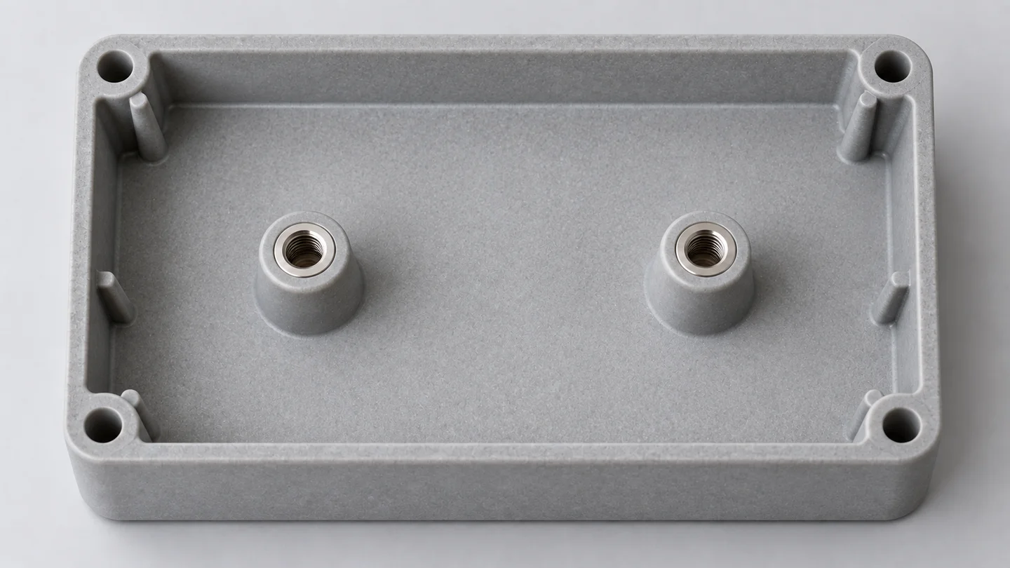
- After molding: accessible thread condition, insert position and angle relative to the agreed part references.
- For the application: assembly fit and any required retention testing, using agreed loads and acceptance criteria.
If the bracket still does not seat, record whether the discrepancy follows one insert, one cavity or a particular loading condition. That evidence helps distinguish a locating issue from a change in the molded part's geometry. It avoids changing the tool on the assumption that every assembly mismatch is an insert fault.
A useful trial agreement with SUASE should identify the sample condition, inspection references and evidence needed for each check. One successful bracket installation is a starting observation; repeatable results under the agreed conditions are what support a production decision.
Bring the insert and part drawings into the same conversation
Starting a BMC insert-molding project, or trying to resolve a bracket that will not fit? Begin with an available part drawing or a sketch marking the mismatch. SUASE can use that starting point to discuss which locating and loading features need closer review. Insert details, mating references and the loading method can then be added as the tooling discussion develops.
This lets the discussion with SUASE focus on a concrete result: a tool concept in which functional location, practical loading and finished-part inspection agree. It is a stronger basis for tooling development than requesting a “high-precision BMC mold” without defining what the assembly actually needs.